PicoRC
PicoPSU Adaptor for Apple IIGS
| Purchase Link | Official Discord | Table of Contents |
This adaptor lets you use Pico ATX PSU in Apple IIGS computer.
It replaces the original PSU, and uses very common 12V power brick instead.
Highlights
- Non-destructive and reversible
- PC fan header for added cooling
- Universal voltage with fused rails
- Low cost, efficient and reliable.
Get One / Other Stuff
Also available for Compact Macintosh, Apple IIGS, BBC Micro, Osborne 1, and more.
For more general-purpose diagnostics and retrofitting, check out the full-fat ATX4VC.
Table of Contents
Getting a Pico PSU
PicoPSUs are tiny ATX power supplies for small PCs, but perfect for retro computers as well.
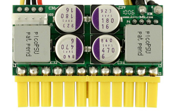
- Official website and distributors.
- The cheapest 80W one should be plenty.
- Avoid generic clones
- They over-rate and are of low quality.
- A power brick with 12V DC and center positive 5.5x2.5mm barrel jack is needed.
- They are very popular and you might already have one.
- Make sure it has enough wattage.
Remember that this solution is only as good as your PicoPSU and 12V Brick, so don’t skimp on them!
Kit Assembly
DON’T START YET!!! Keep reading :)
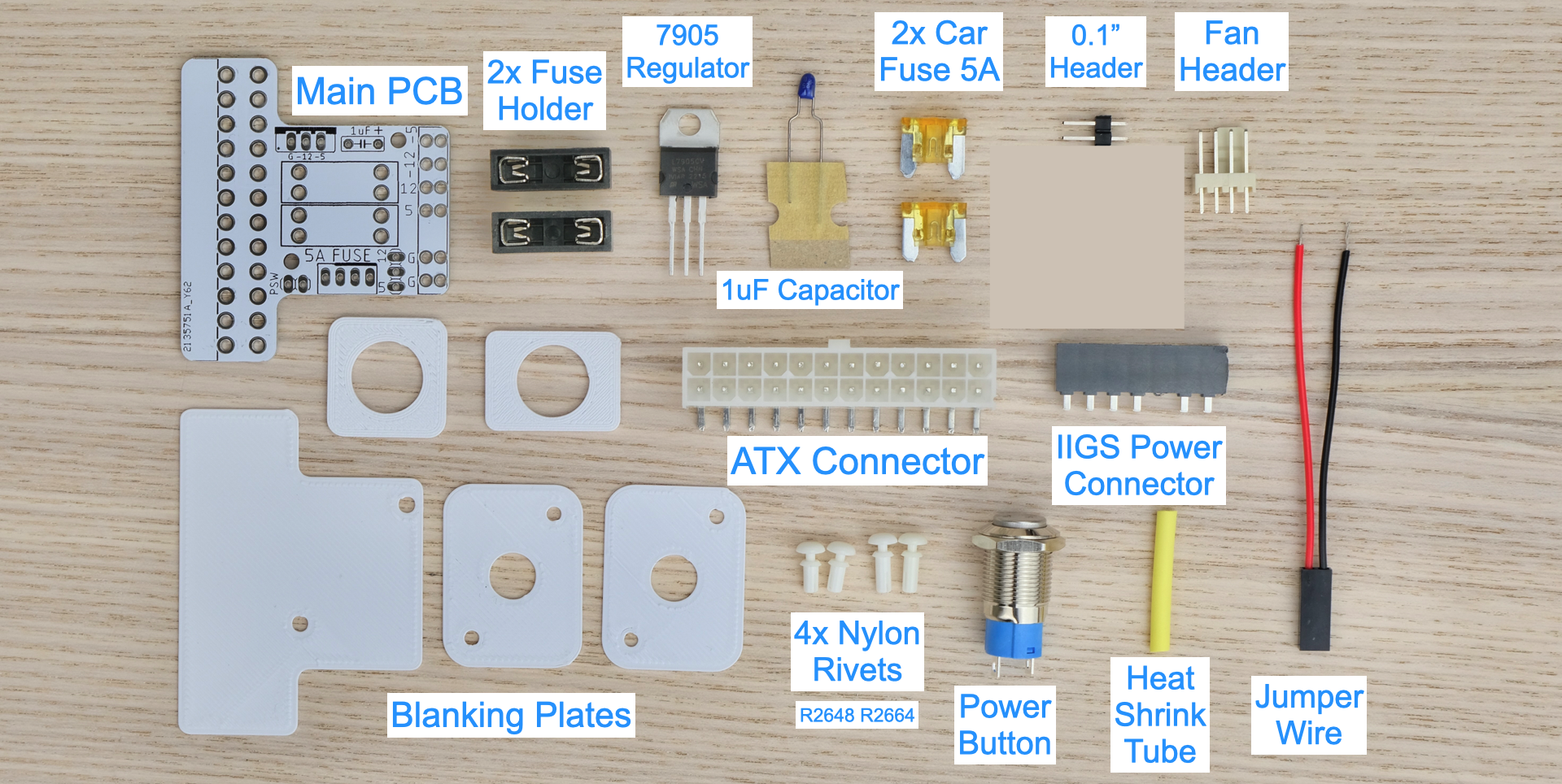
Observe the parts:
Soldering Notes
Nothing too tricky in this kit, all basic through-hole parts.
If this is your first time:
- Ensure your soldering iron has proper temperature control
- Try your local makerspace or university lab
- Use leaded solder and plenty of flux
- Temperature around 350C / 660F.
- This video covers the basics pretty well
- Start from shortest to tallest.
- Solder a single pin first, ensure it is straight, adjust if necessary.
Assembly
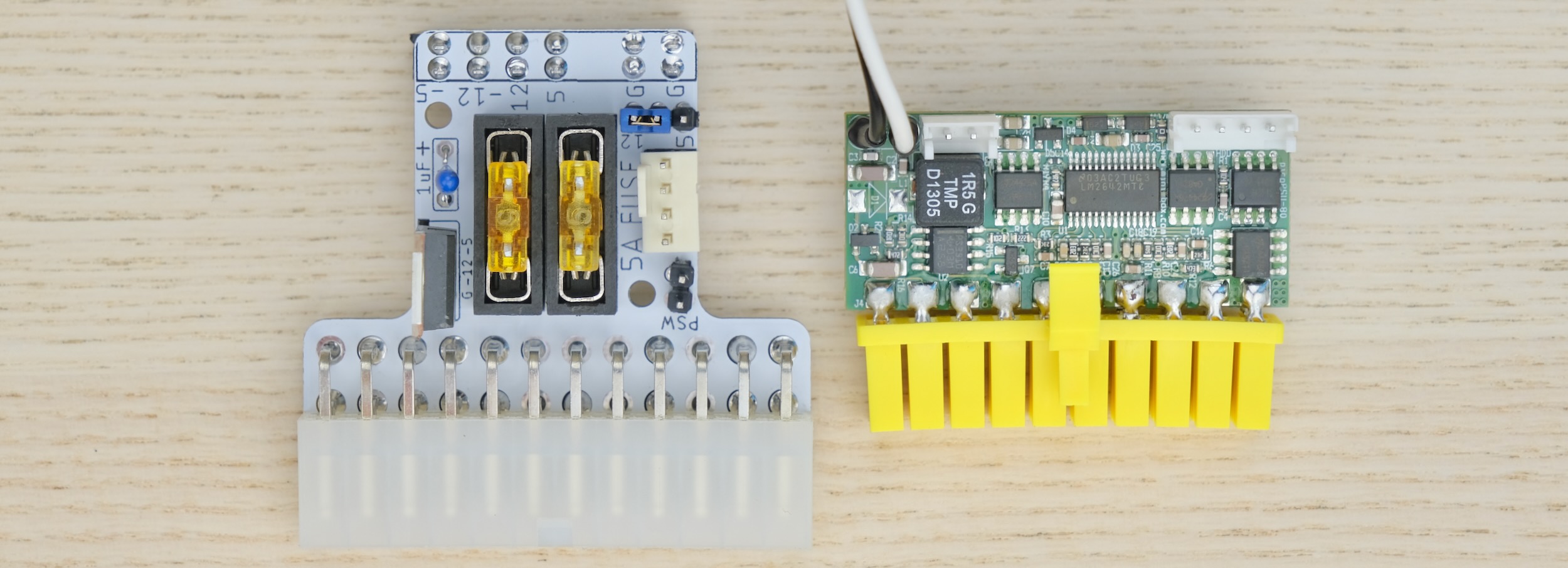
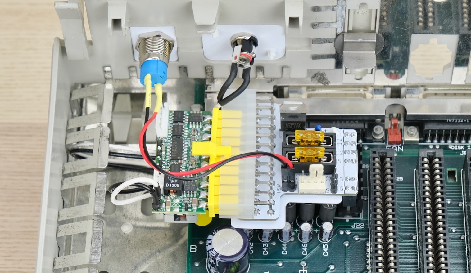
Solder the main PCB as shown below, follow the notes:
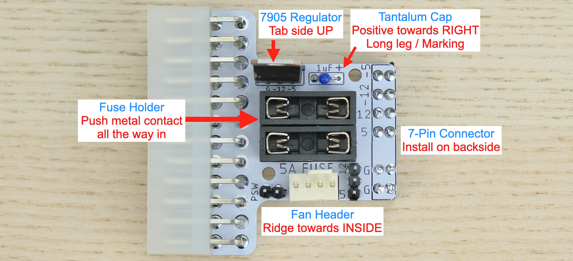
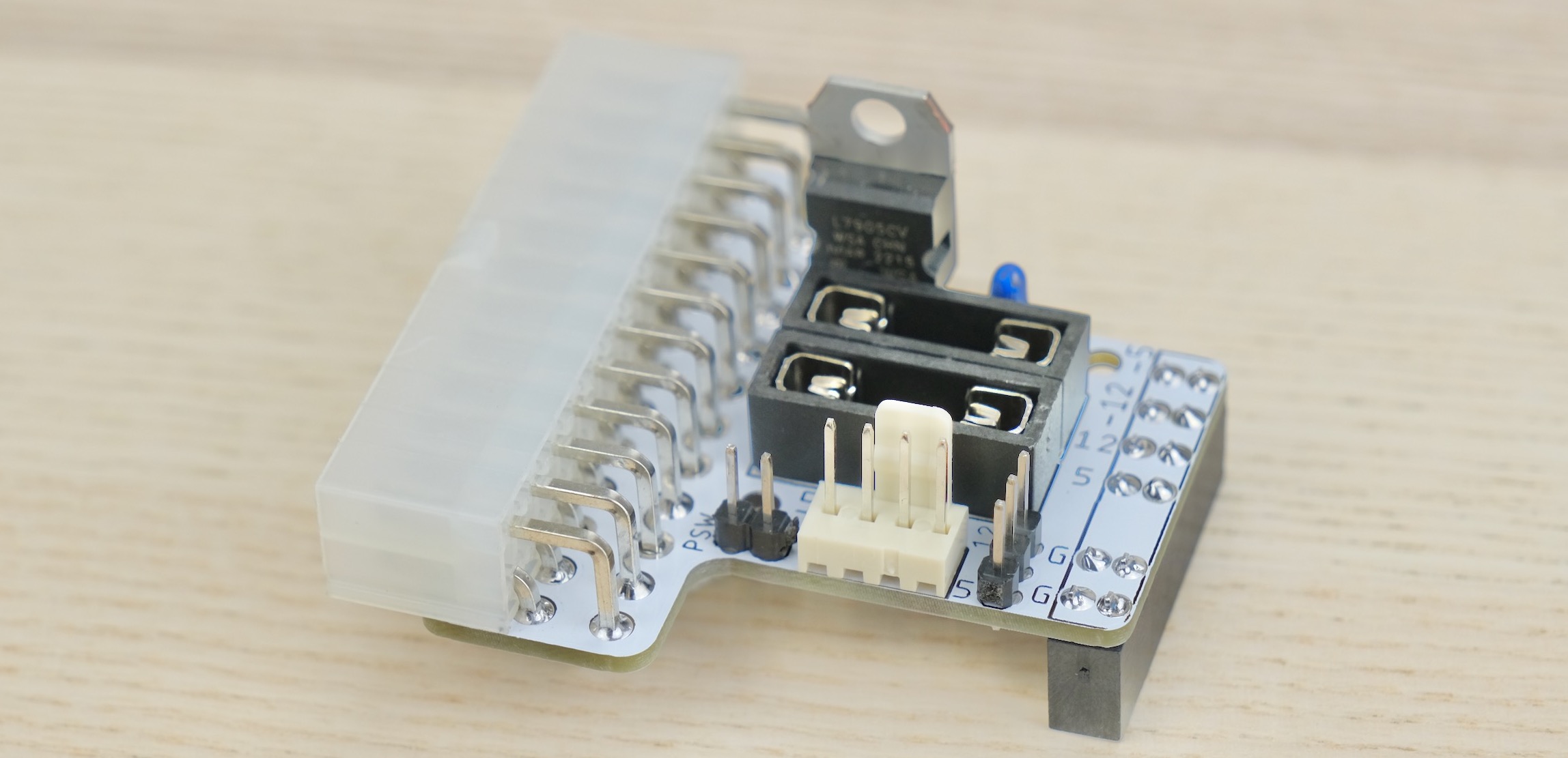
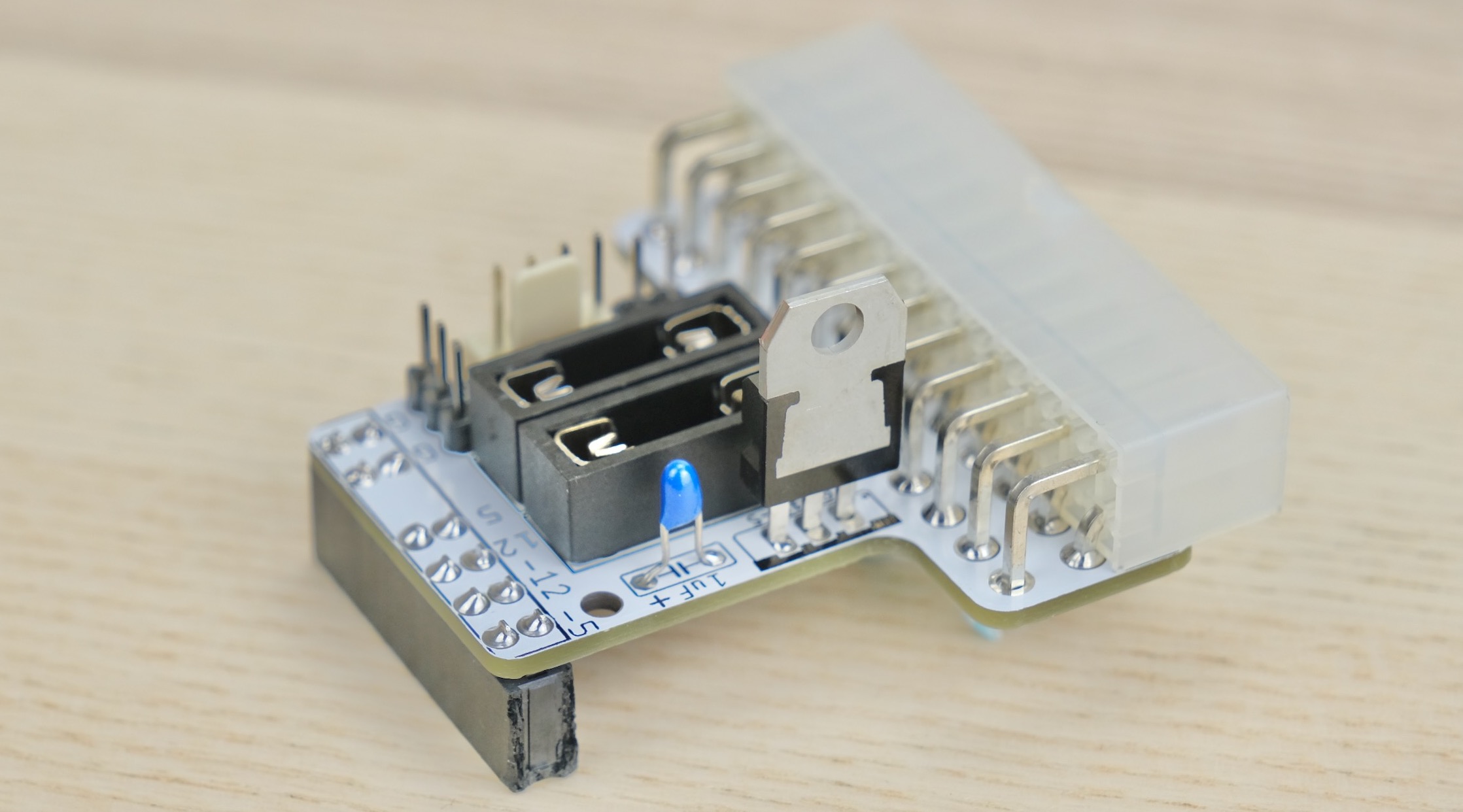
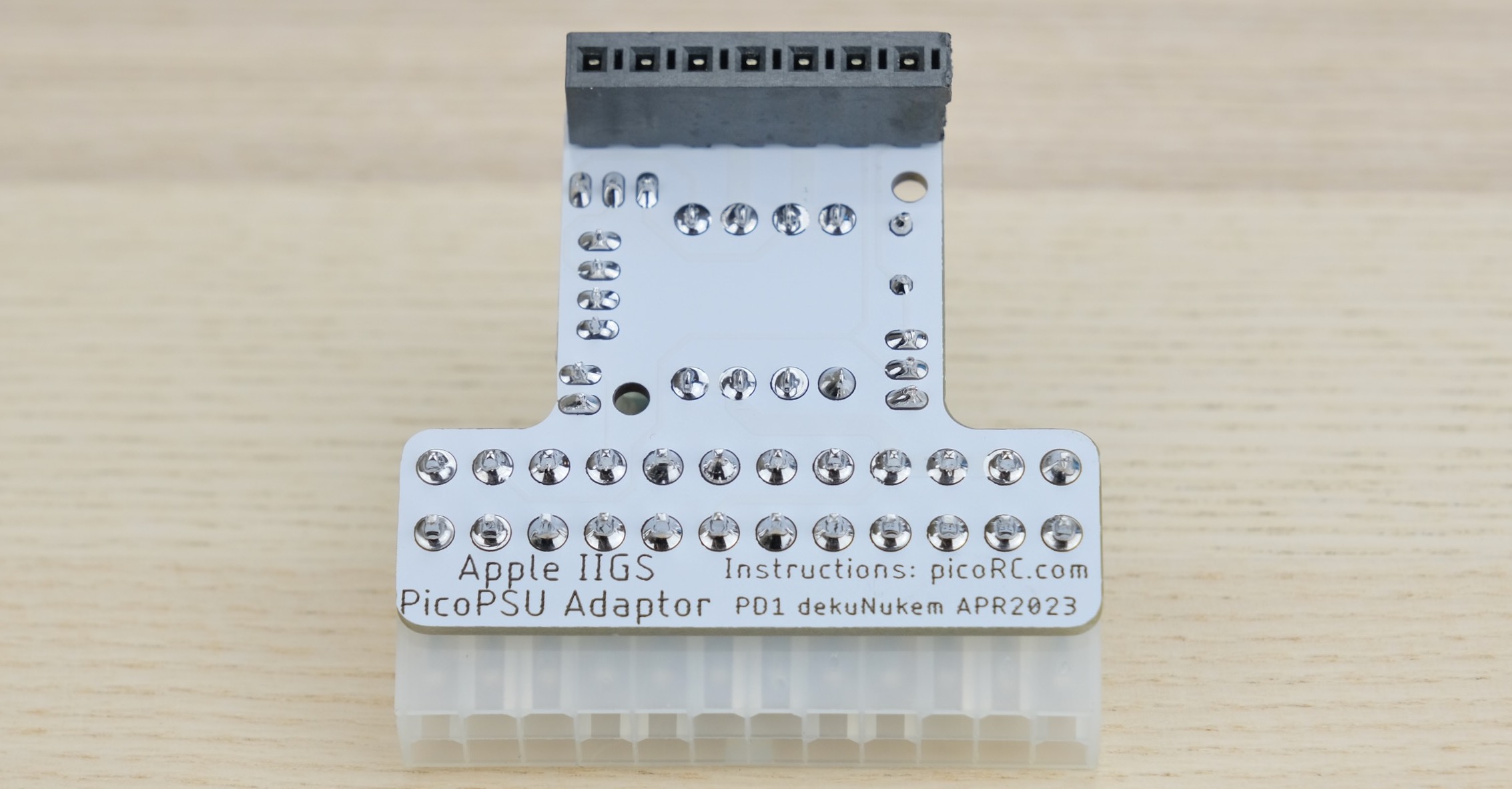
More reference photos:
Cleaning
Optional, but I like to clean off the flux with 90%+ isopropyl alcohol.
Submerge and scrub with a toothbrush.
Make sure it is completely dry before proceeding.
Inspection
- Compare with reference photos above/below.
- Solder joints should be shiny and smooth.
- There must be no solder bridges.
- If any, add flux and melt to remove.
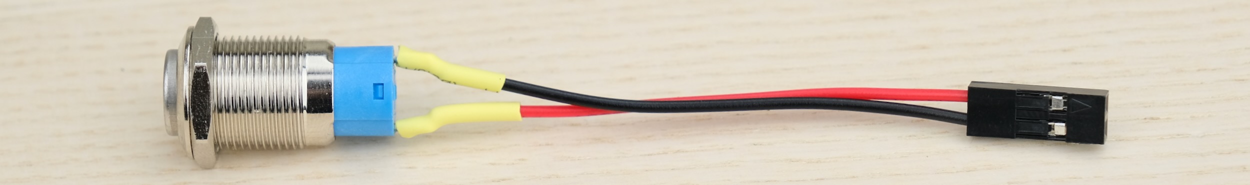
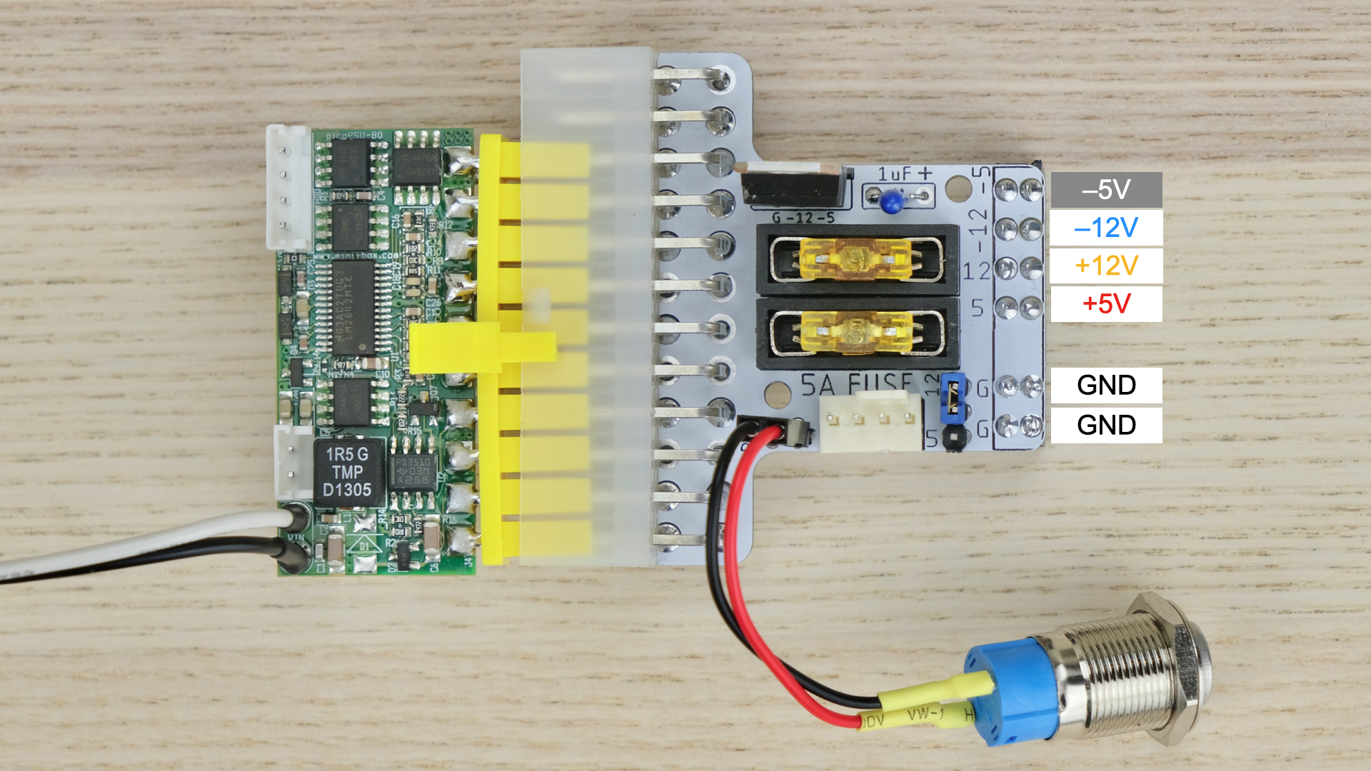
Power Button
- Insert heat shrink tube through both wires.
- Solder the wires to the button.
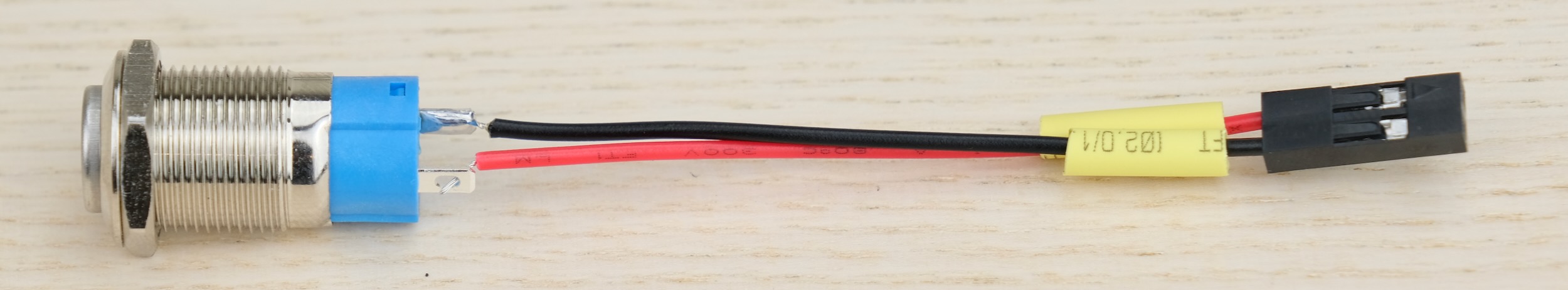
- Slide the tubing up to cover the contacts.
- Use hot air to shrink.
- Install two fuses
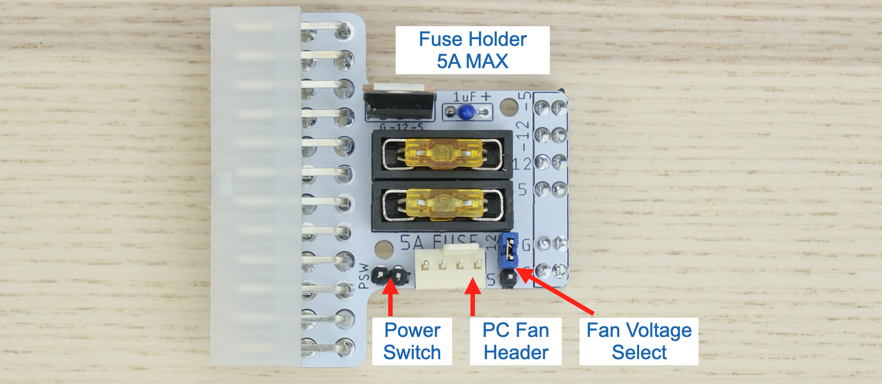
PC Fan Header:
- Any standard 3 or 4-pin PC fan will work
Fuse:
- Use common car fuse
- Rated 5A OR LESS
- DO NOT BYPASS FUSES
Pre-flight Checks
Use a multimeter to check for dead shorts between each power pin and GND:
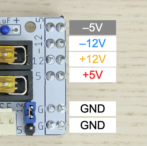
If all good, plug in PicoPSU and connect the power button, turn it on.
Measure the voltage on each rail and confirm they are within spec.
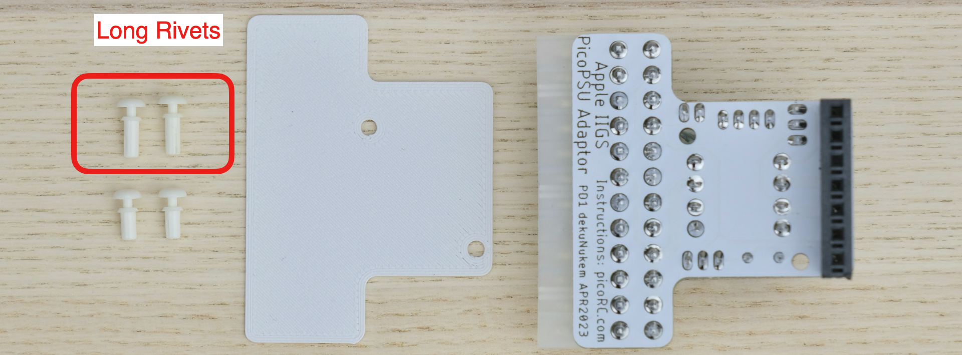
PCB Backplate
This is to prevent short circuit on nearby components.
There should be four nylon rivets.
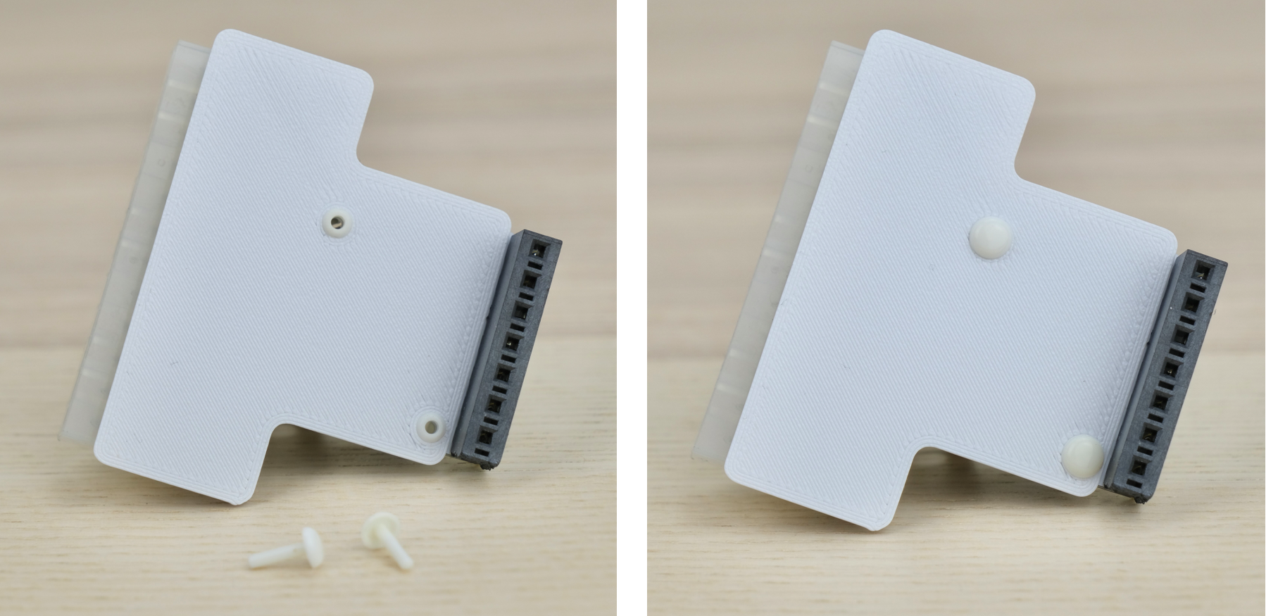
Use the two longer ones for this.
- Pull them apart
- Insert the hollow tube from bottom side
- Insert the plunger to secure in place
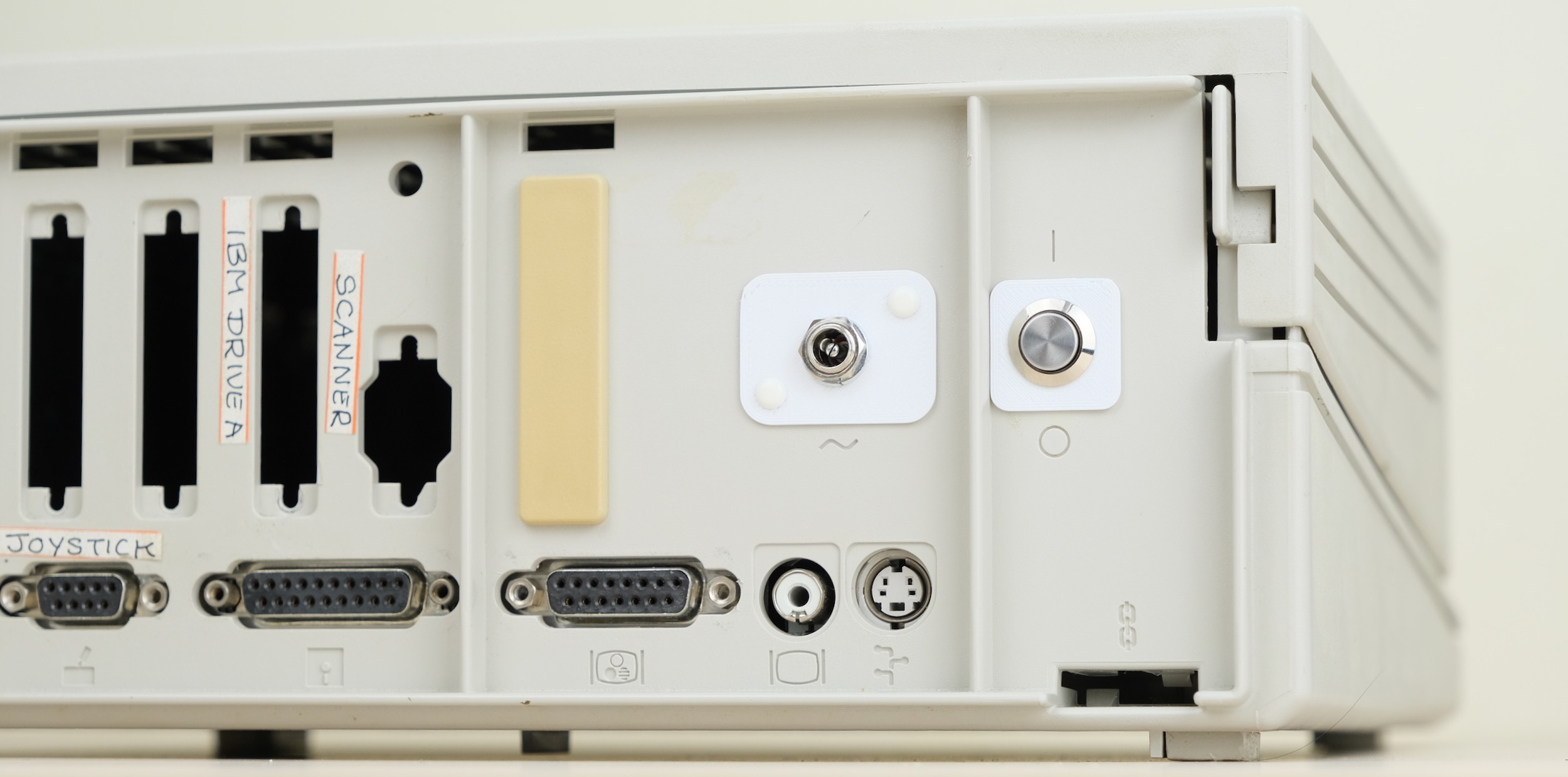
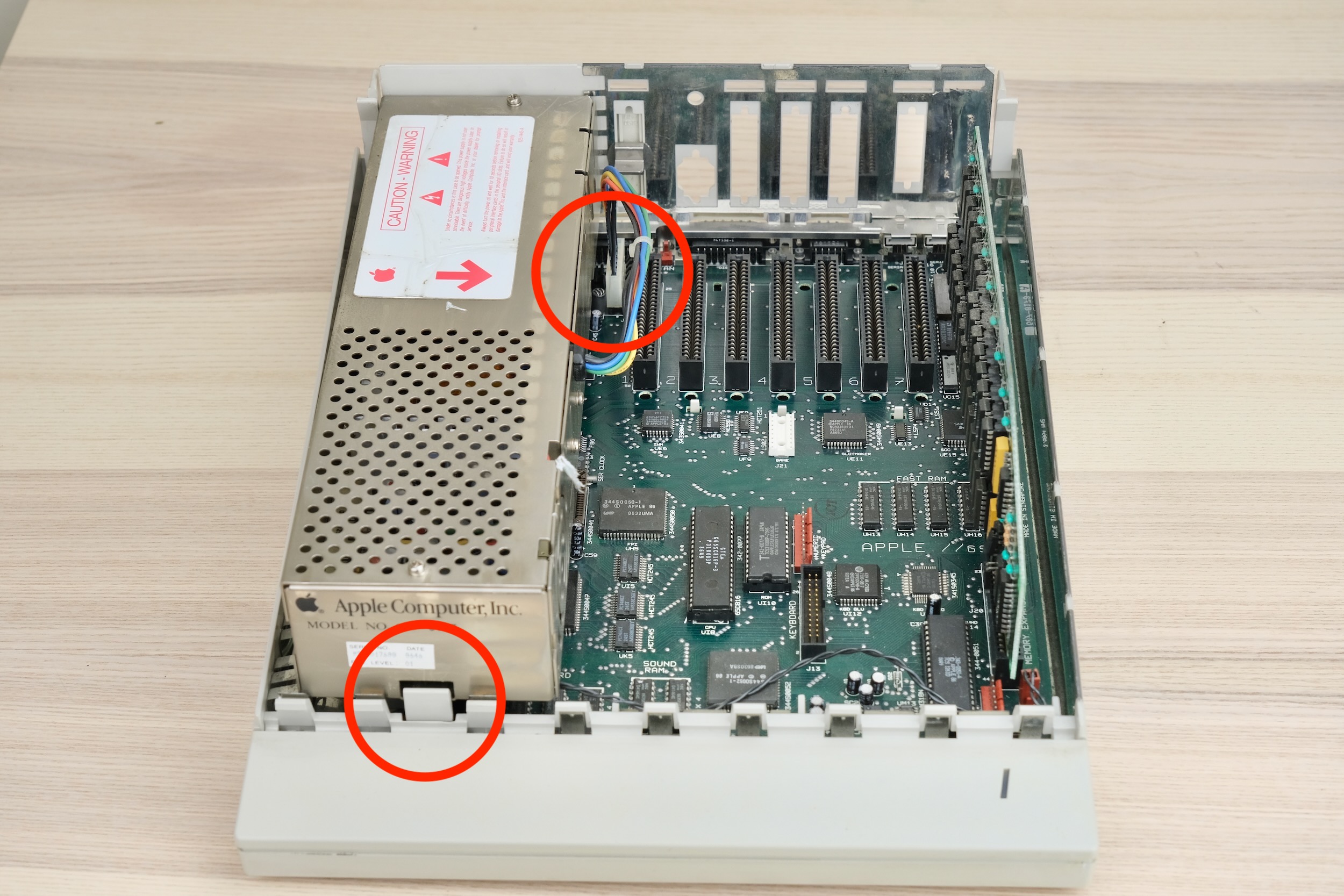
Installation
- Remove top cover
- Pull back the tab to release old PSU
- Unplug cable
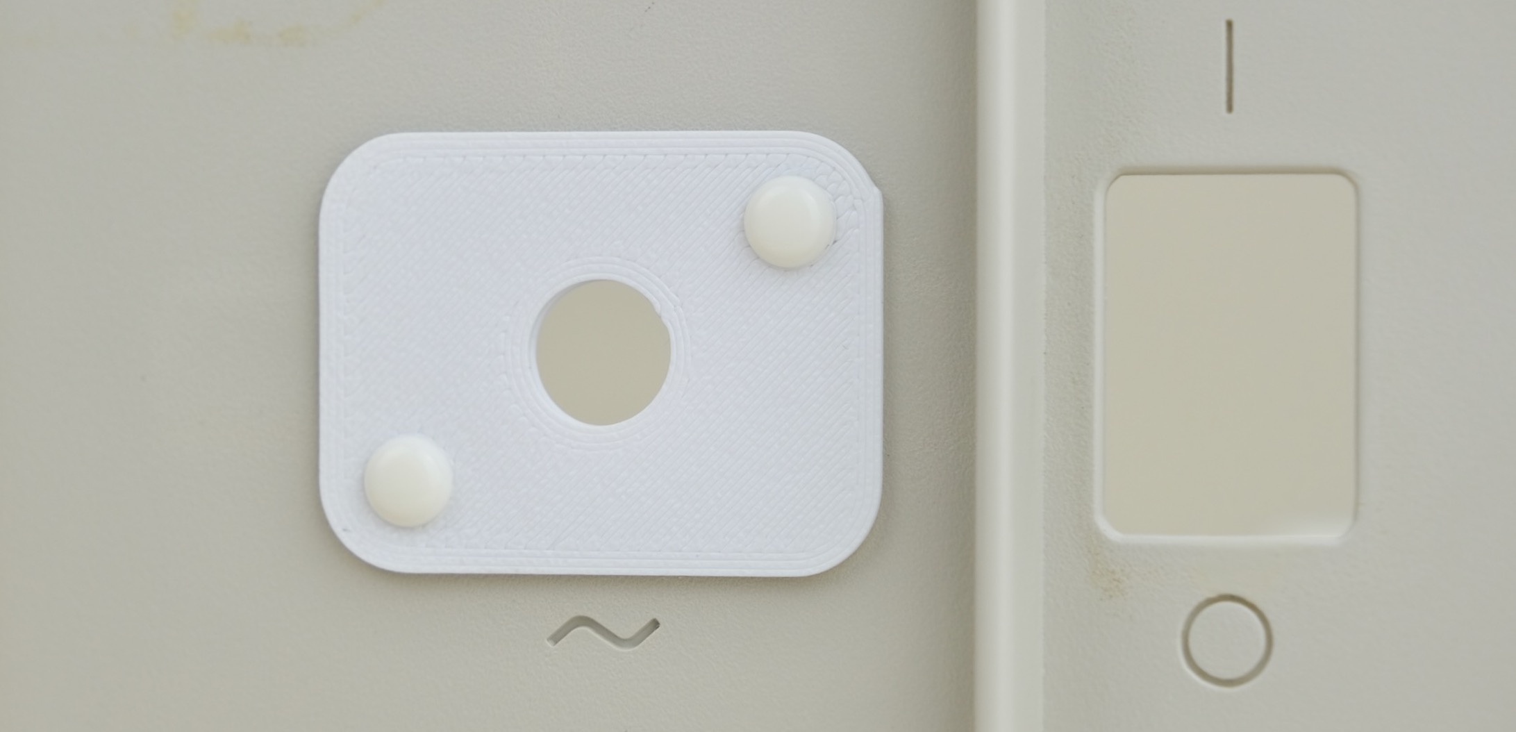
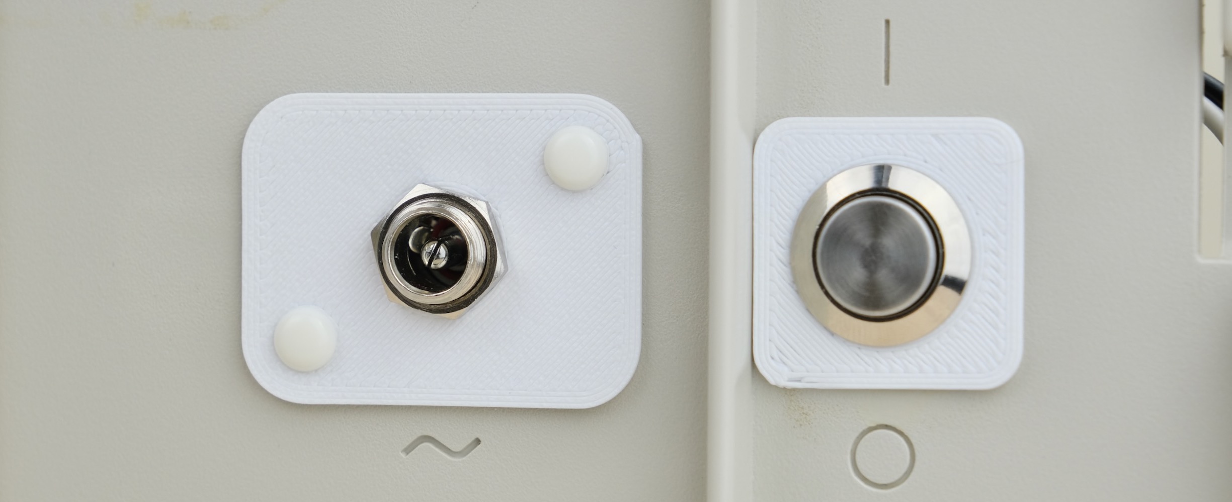
- Get the power jack plates, place one inside.
- Pull apart the rivets like last time
- Insert the hollow tube on the outside plate
- Line up and make sure it goes through both plates
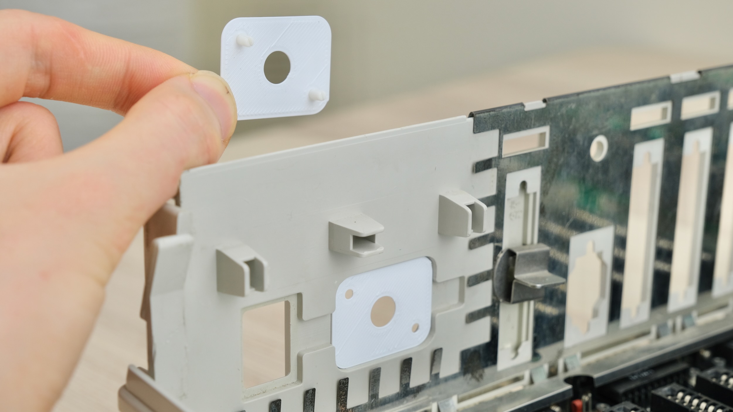
- Support the other side with your hand
- Insert the plunger to hold it in place
- Next up, power button.
- Gather all the parts. Undo the locking ring.
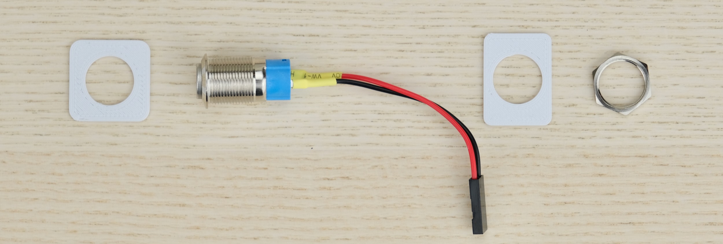
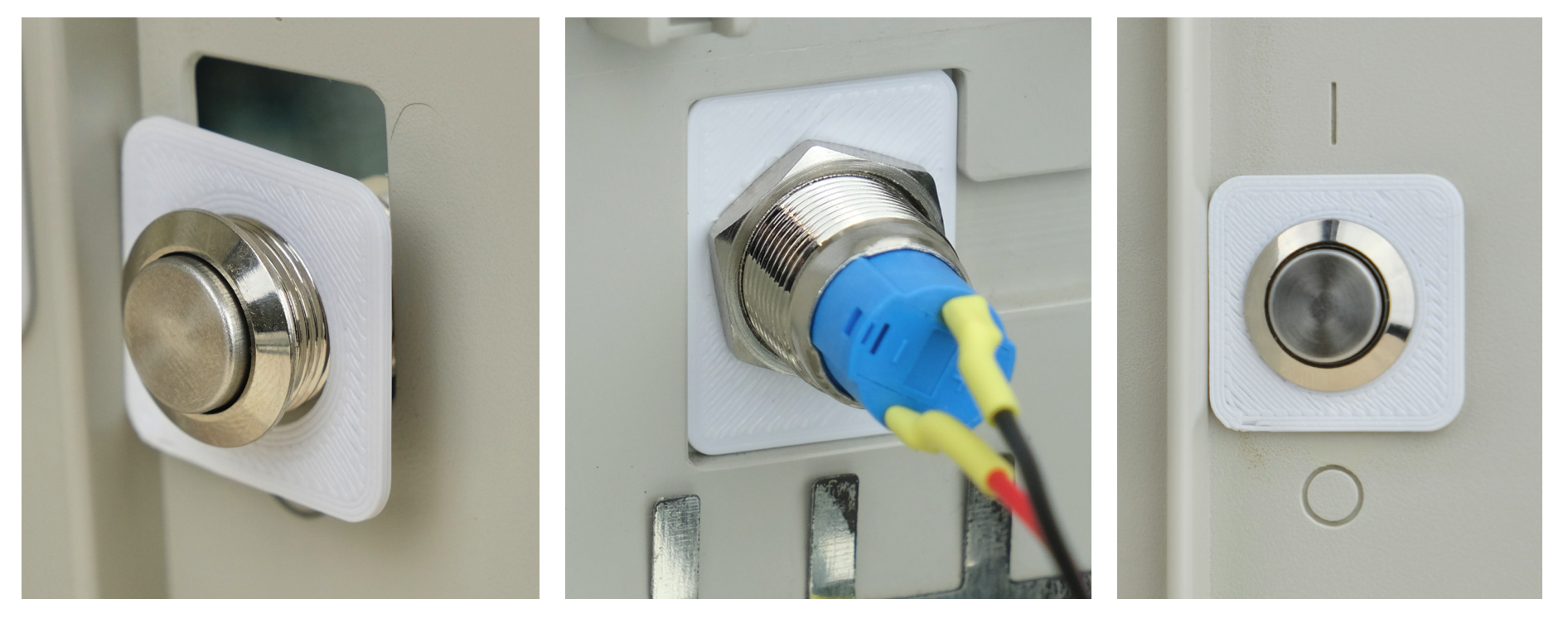
- From outside, insert the button through the square plate.
- From inside, install the rectangle plate, then tighten with the locking ring.
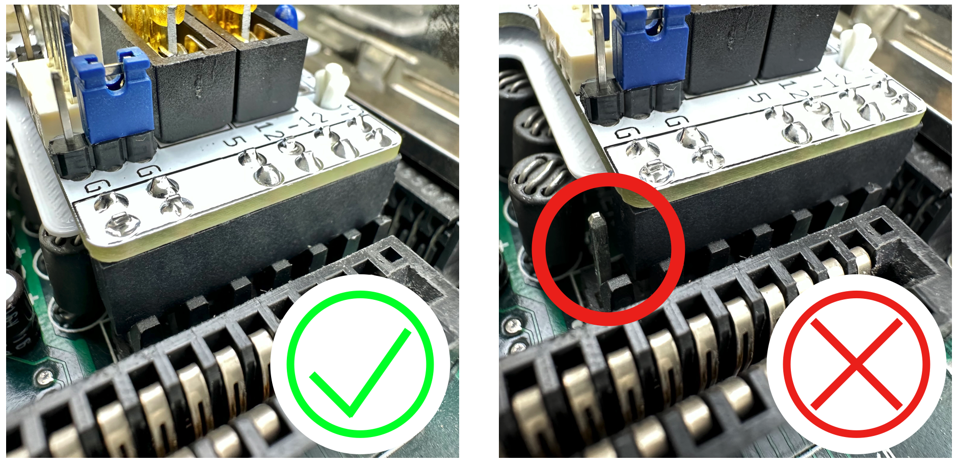
- Plug the assembly into the motherboard power connector
- It should go in firmly, but NOT reach the bottom.
- Plug in the power button
- Double check on both sides that pins are lined up and NOT off-by-one!
- Undo the locking ring on the barrel jack, insert through hole, reinstall on the outside.
That’s pretty much it!
Adding a Fan
You can add a fan for additional cooling. Any regular PC fan should work.
Ensure:
- Fan is mounted securely
- Nothing touches the blade
- Air flow direction is correct
Congratulations!
Put the cover back on, and you’re done!
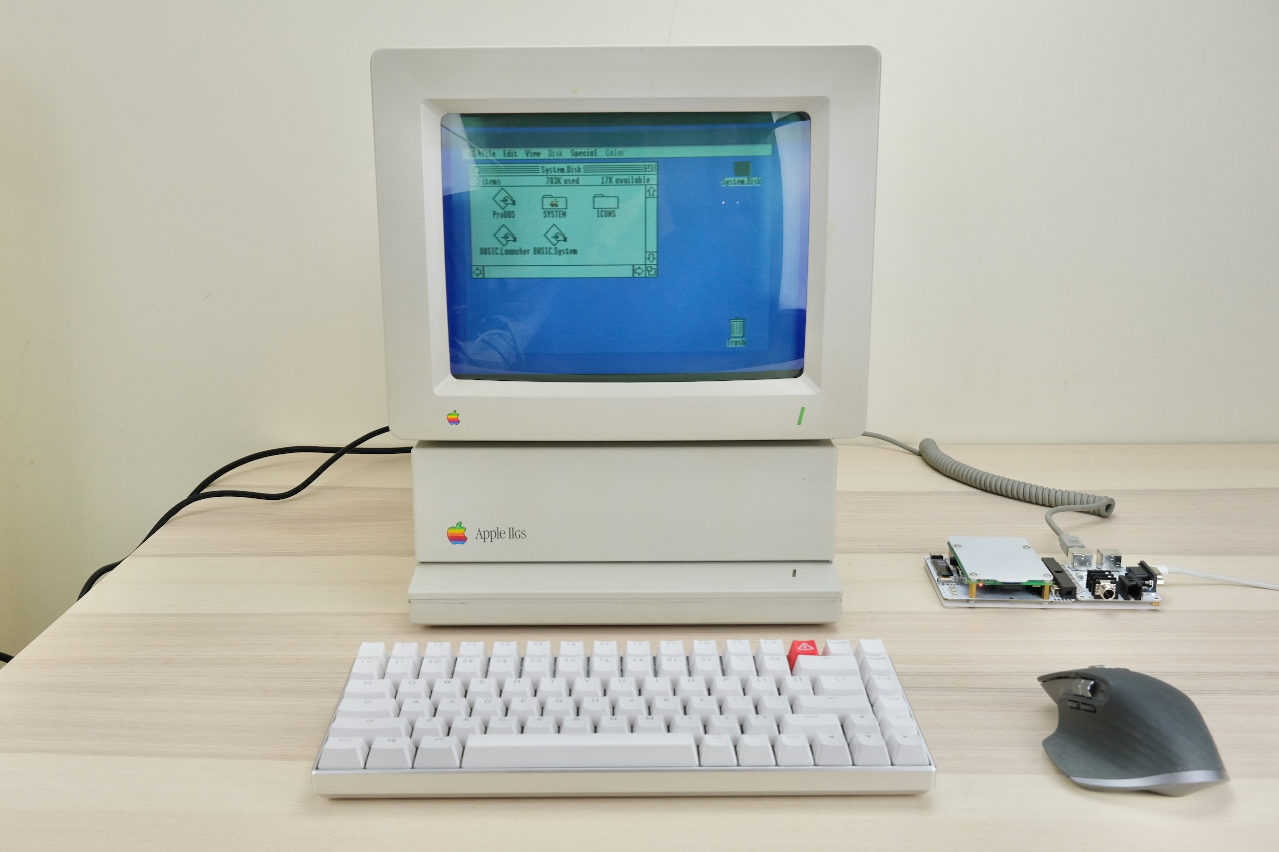
What’s with the wireless keyboard and mouse? Check out USB4VC!
Questions or Comments?
Feel free to ask in official Discord Chatroom, raise a Github issue, or email dekunukem gmail.com!