PicoRC
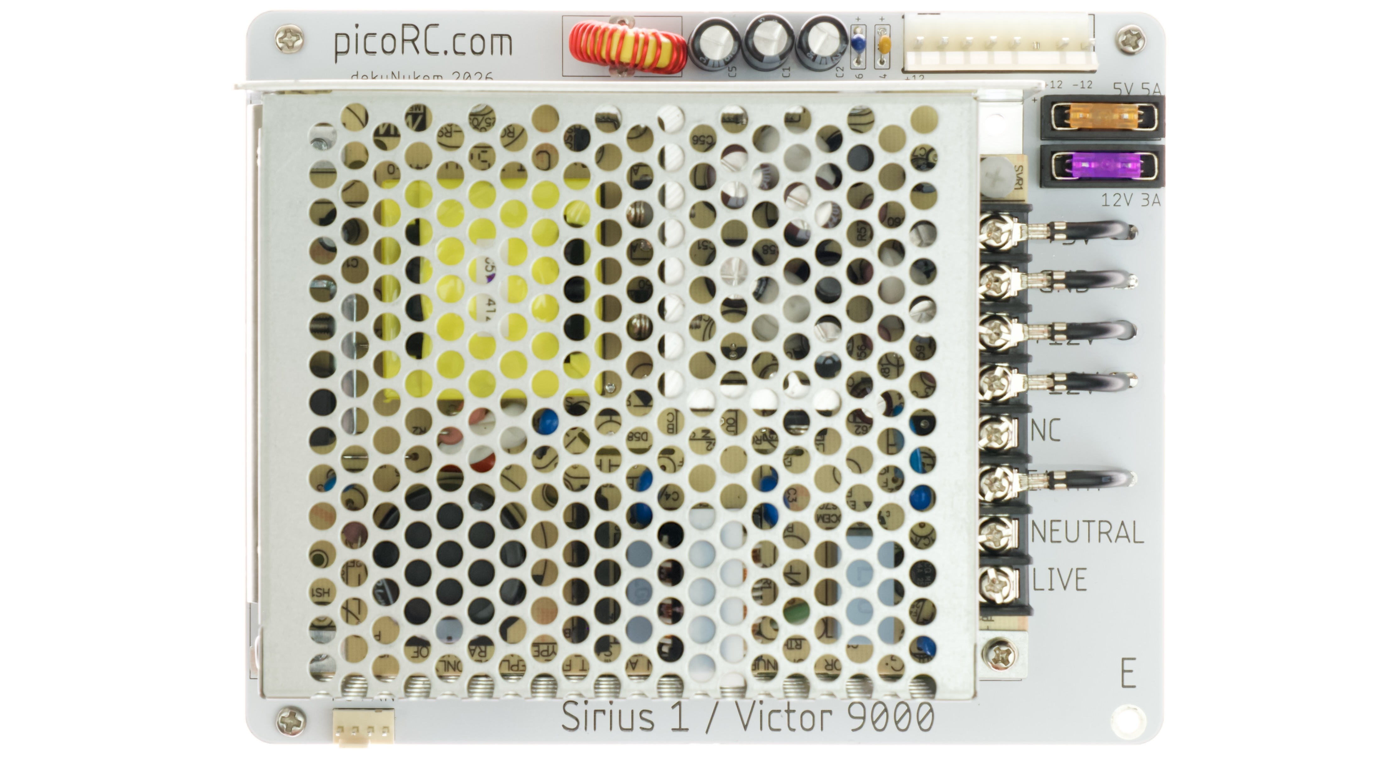
PicoRC PSU Kit for Sirius 1 / Victor 9000
| Purchase Link | Official Discord | Table of Contents |
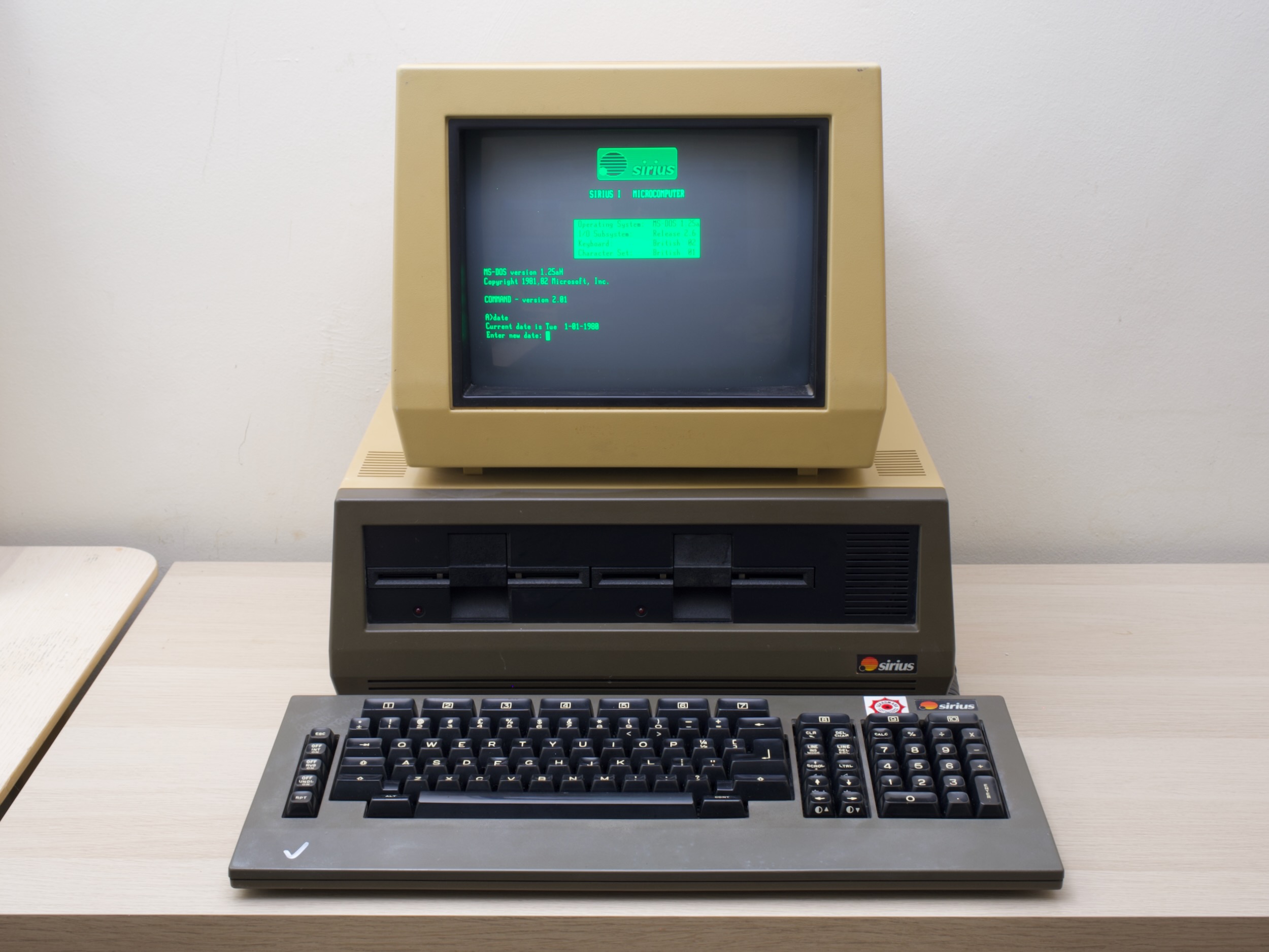
A replacement PSU kit for Sirius 1 / Victor 9000 Computers
- Non-destructive and Reversible
- Reuses Existing Hardware
- Original Appearance
- Modern PC Fan Support
- Quieter & improved cooling
- Mean Well PSU with Fused Rails
- Low-cost and reliable
Get One
Also available for many other computers.
For more general-purpose diagnostics and retrofitting, check out ATX4VC.
Shopping List
Apart from the kit itself, you need two more items:
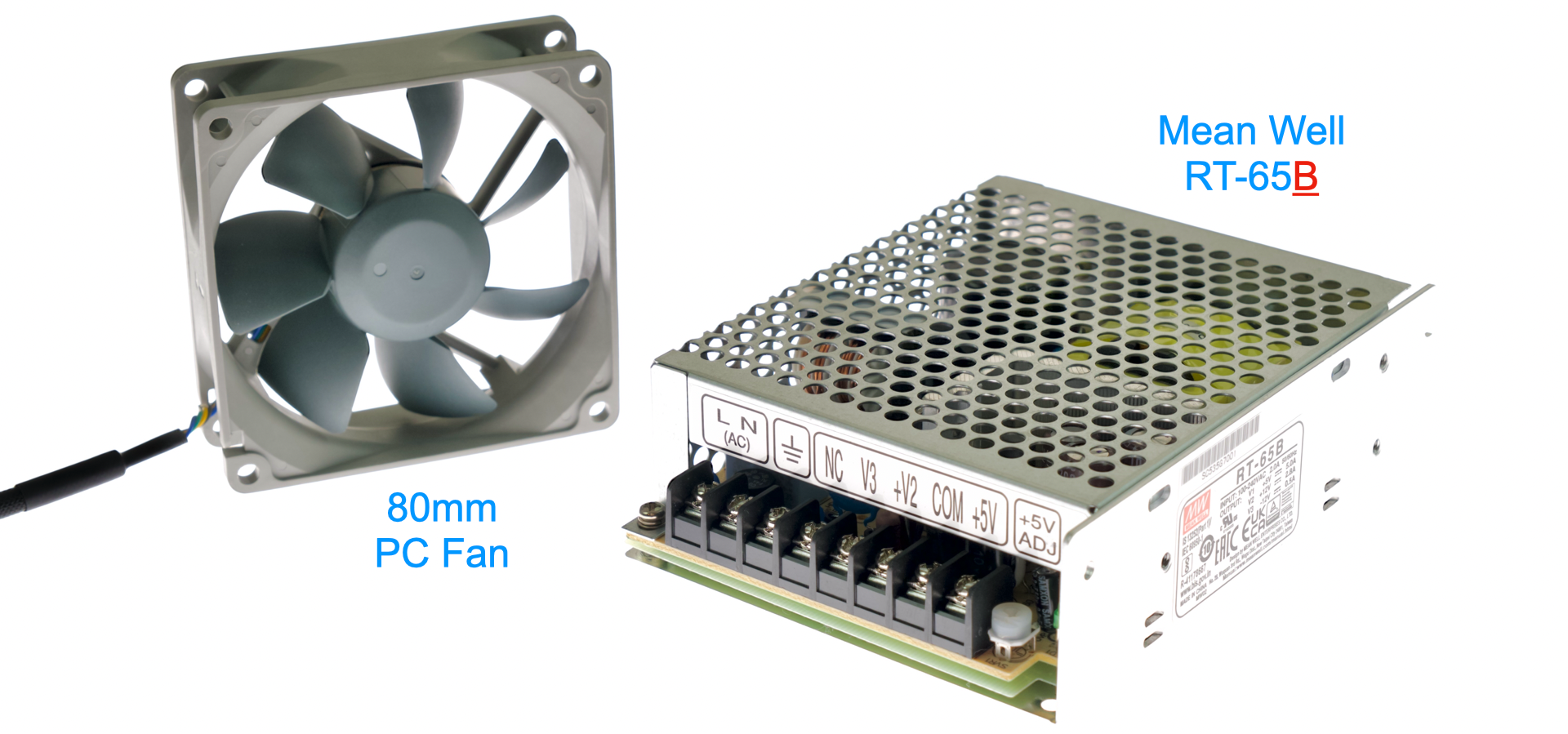
Mean Well PSU
This kit uses Mean Well RT-65B Chassis Mount PSU.
⚠️ ⚠️ MAKE SURE IT IS THE “B” VARIANT! ⚠️ ⚠️
- Inexpensive and good quality
- Around 20 USD / GBP
- Buy from a reputable distributor, NOT eBay or Aliexpress!
- Mouser
- DigiKey
- RS Components, etc.
PC Fan
- Replaces the mains-voltage fan.
- Any 80mm 4-Pin PC fan should work.
- Search on your favorite online marketplace.
Kit Assembly
DON’T START YET!!! Keep reading :)
You should have the following:
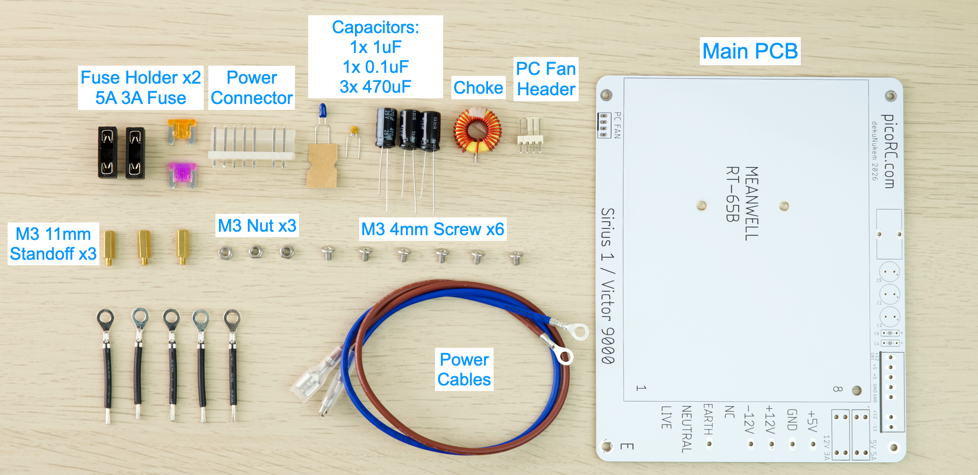
Soldering Notes
Nothing too tricky in this kit, all basic through-hole parts.
If this is your first time:
- Ensure your soldering iron has proper temperature control
- Try your local makerspace or university lab
- Use leaded solder and plenty of flux
- Temperature around 350C / 660F.
- This video covers the basics pretty well
- Start from shortest to tallest.
- Solder a single pin first, ensure it is straight, adjust if necessary.
Assembly
- Solder the components as shown below:
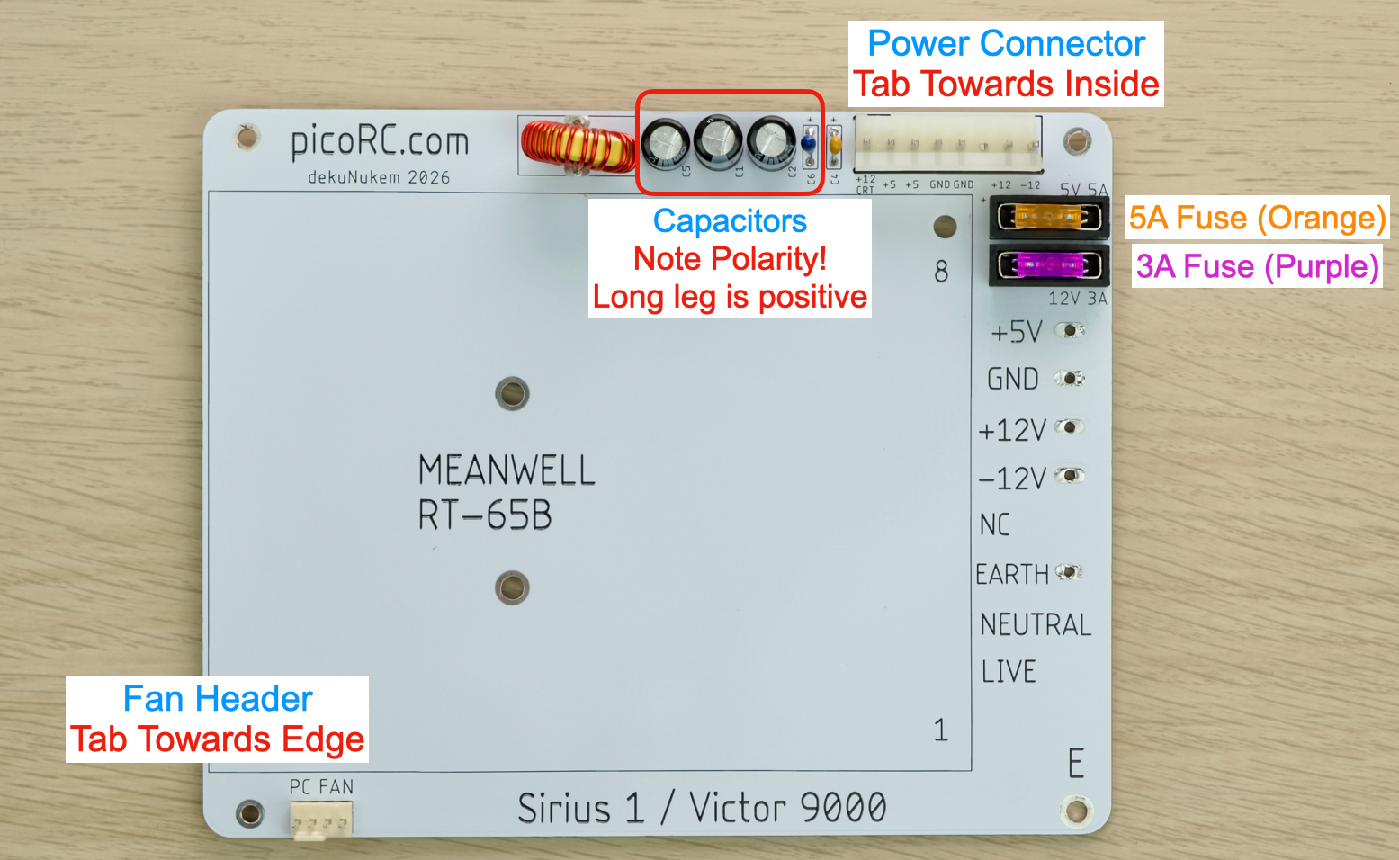
- Double check polarity!
- Black electrolytic capacitor: White stripe is NEGATIVE.
- Blue Tantalum capacitor: White stripe is POSITIVE.
- Yellow ceramic capacitor: No polarity.
- Inductor / Choke: No polarity.
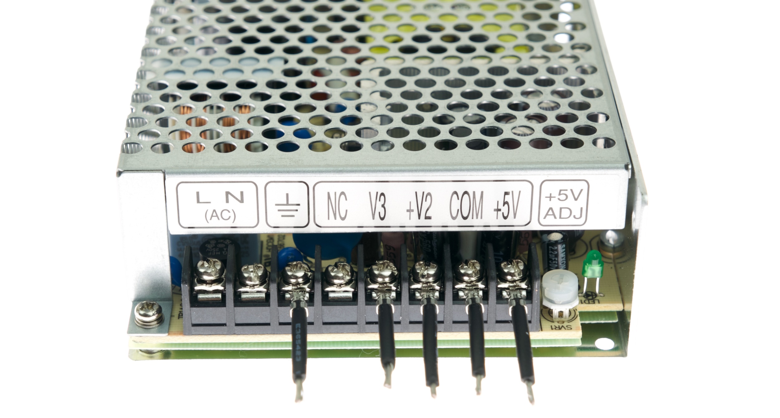
- On the MeanWell PSU, install the ring terminal cable on the rails shown.
- Undo Screw
- Insert through ring (flat side down)
- Redo Screw
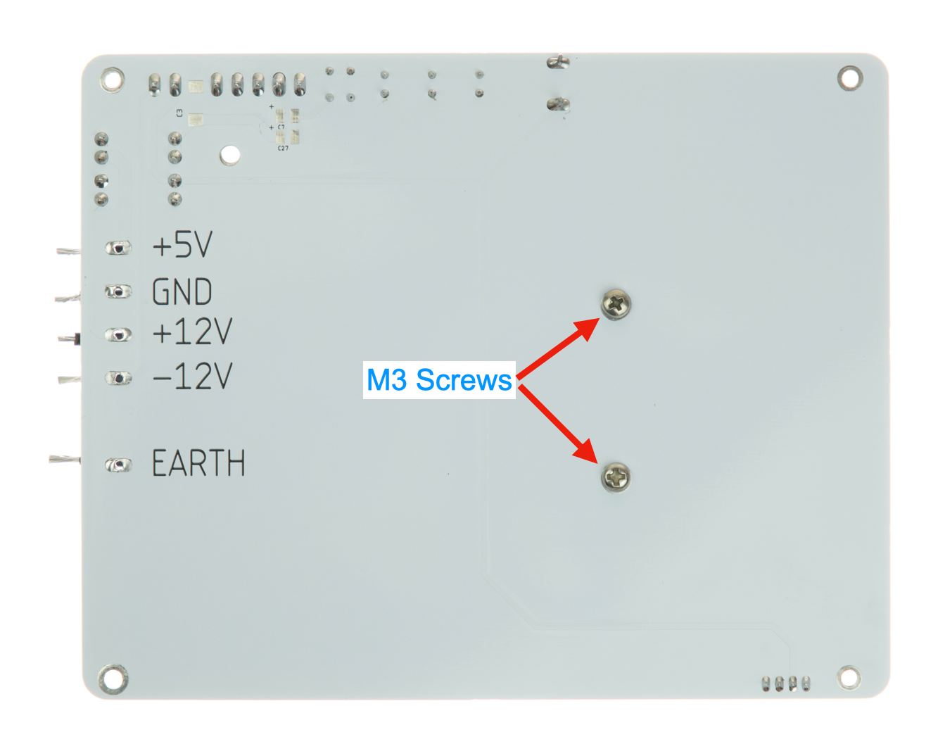
- Fasten the MeanWell PSU to the PCB with M3 screws
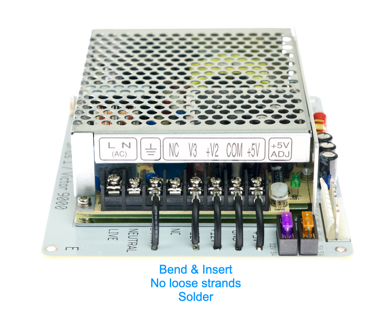
- Bend the wires
- Insert strands through corresponding holes
- Make sure all strands goes through
- And no loose strands being caught on top side
- Solder in place
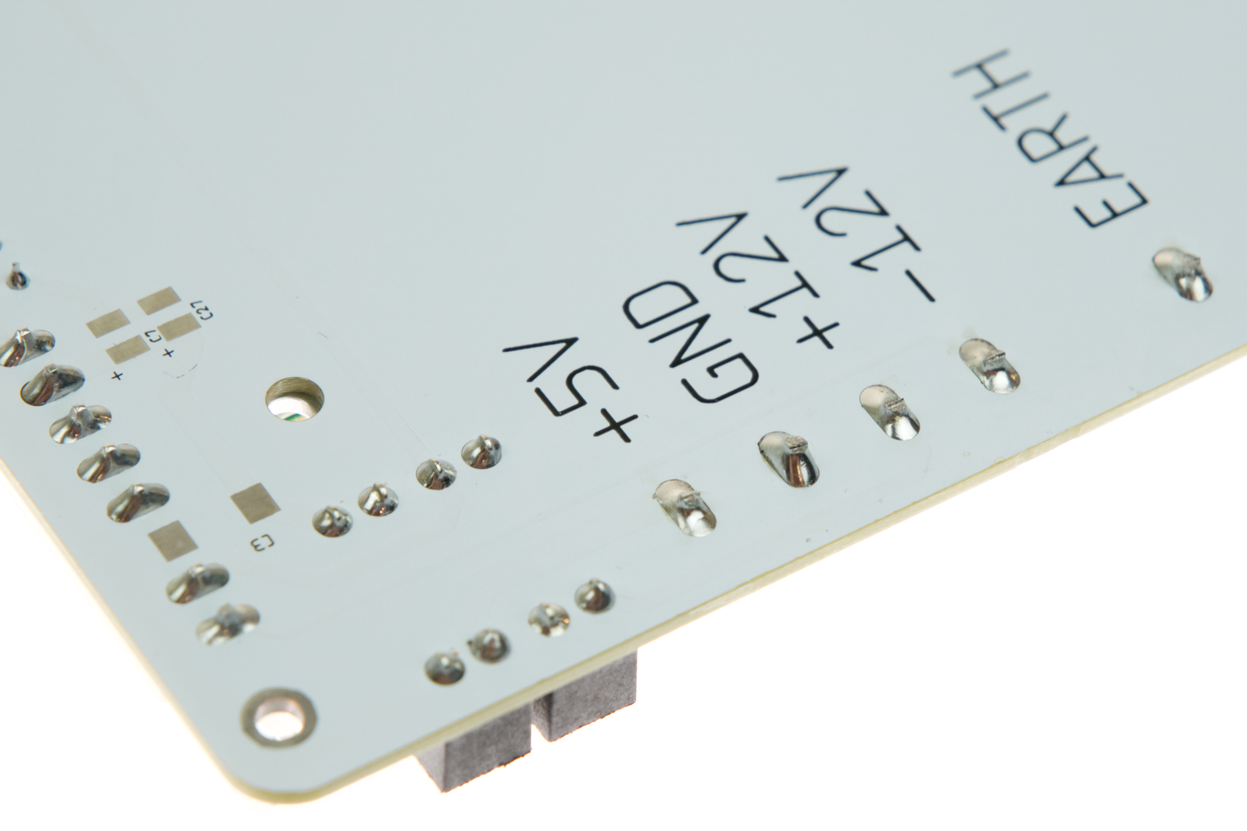
Inspection
- Compare with photos and notes above.
- Ensure everything has correct polarity.
- Solder joints should be shiny and smooth.
- Trim off excess legs
- If you see spikes, put on more flux and melt it again.
- There must be no solder bridges.
Installation
📷 Remember to take plenty of photos as you go! 📷
📷 Take a photo before you remove a screw or unplug anything 📷
🚯 DO NOT throw anything away! Keep the original parts, date and label clearly. 🚯
OK Let’s start!
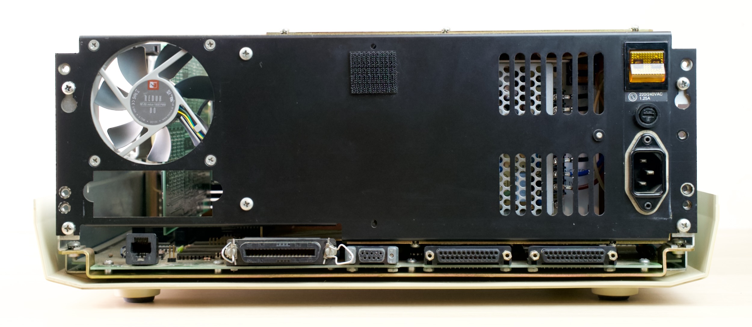
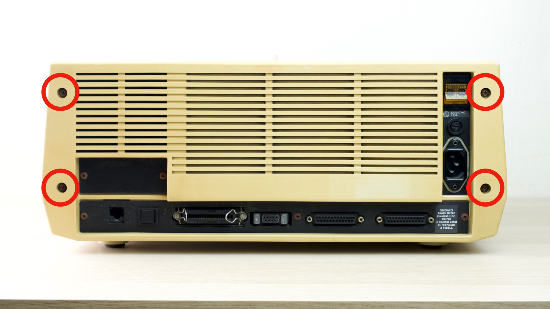
- Remove 4 screws on the back
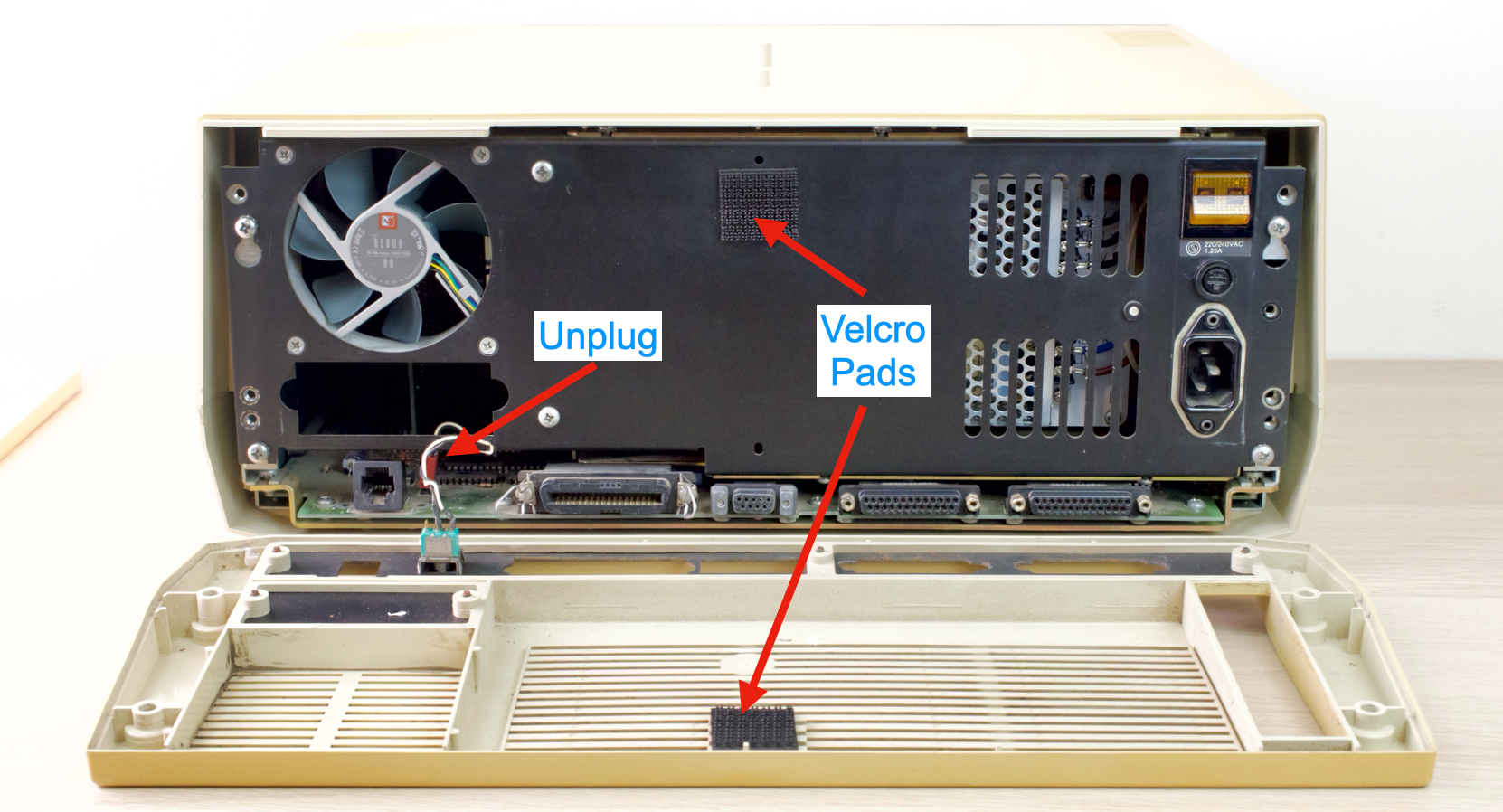
- Unhinge the back cover from top
- Might need a gentle tug due to velcro pads
- Reach in and unplug the reset button
- Remove top cover
- Unplug the power connector
- Remove 5 screws
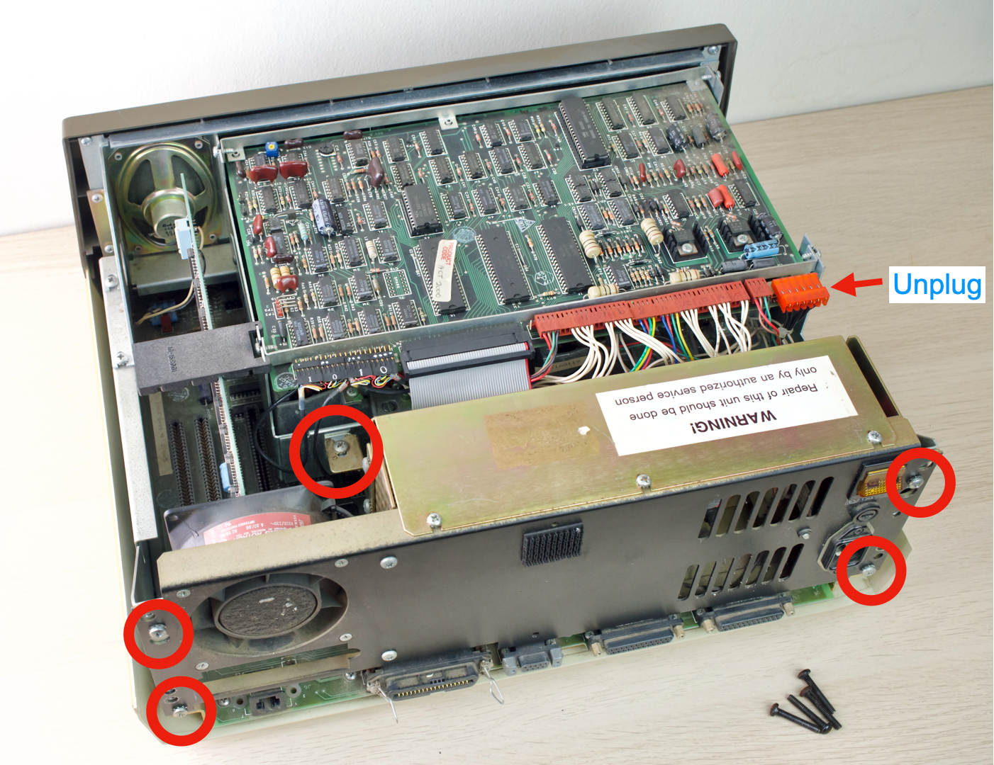
- Rotate PSU away
- Unplug both power connectors
- Remove the PSU completely
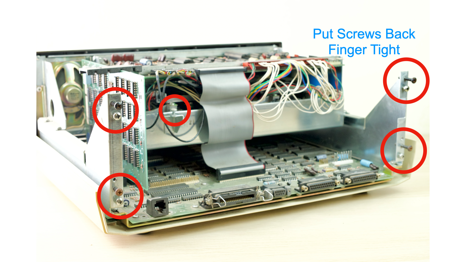
- Insert the screws back in their holes for safekeeping
- Finger tight is fine
- Put the computer away for now
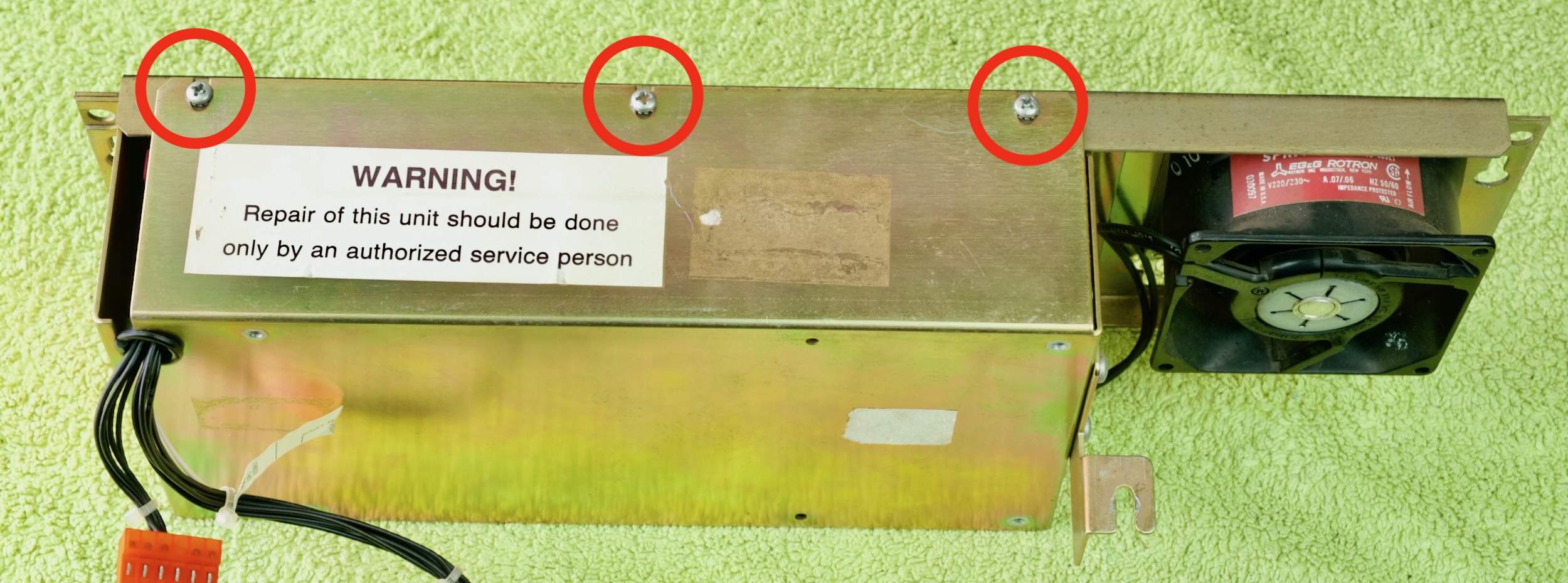
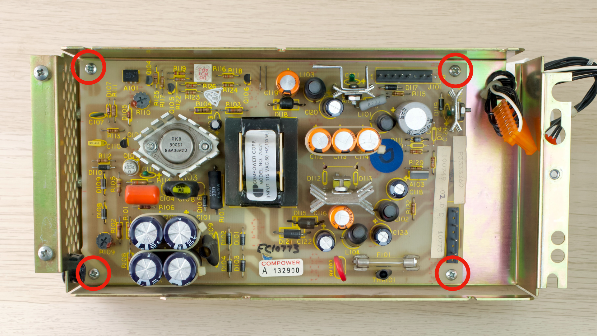
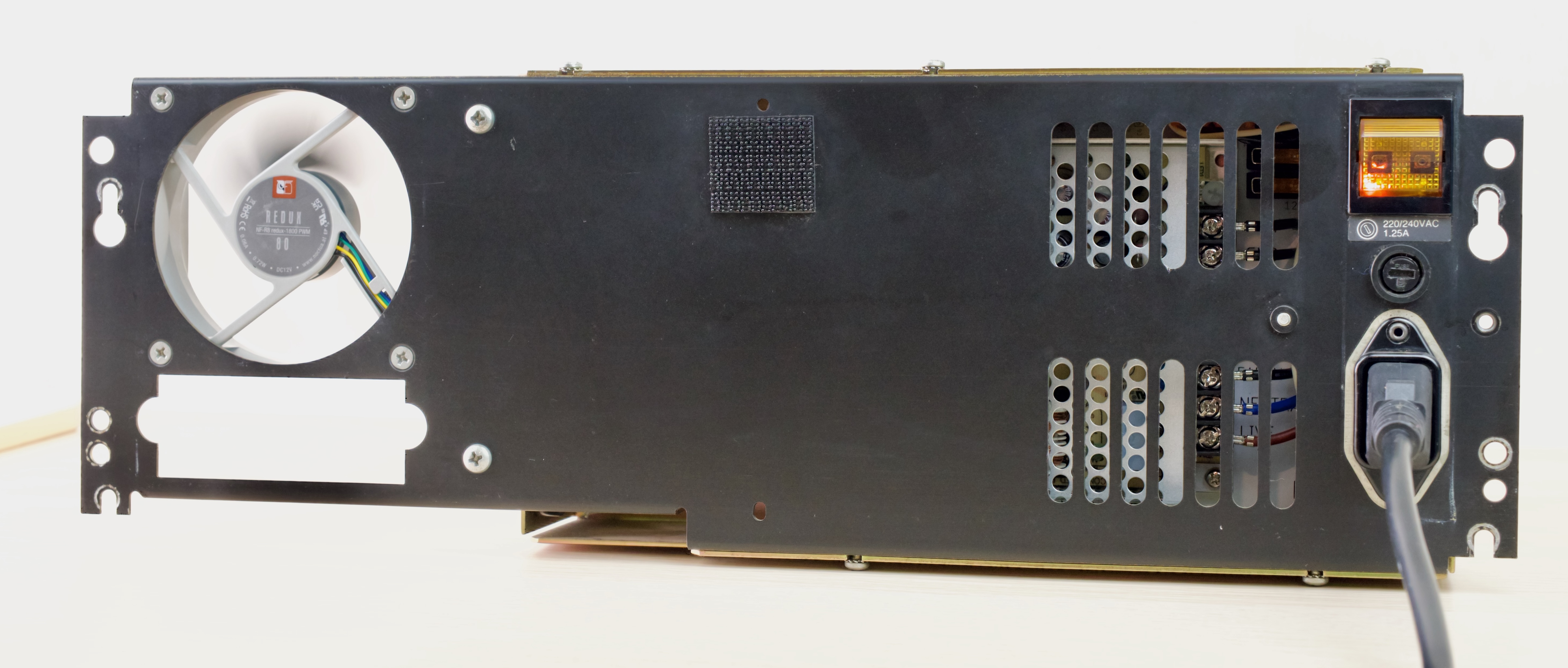
- Remove 7 screws on the PSU
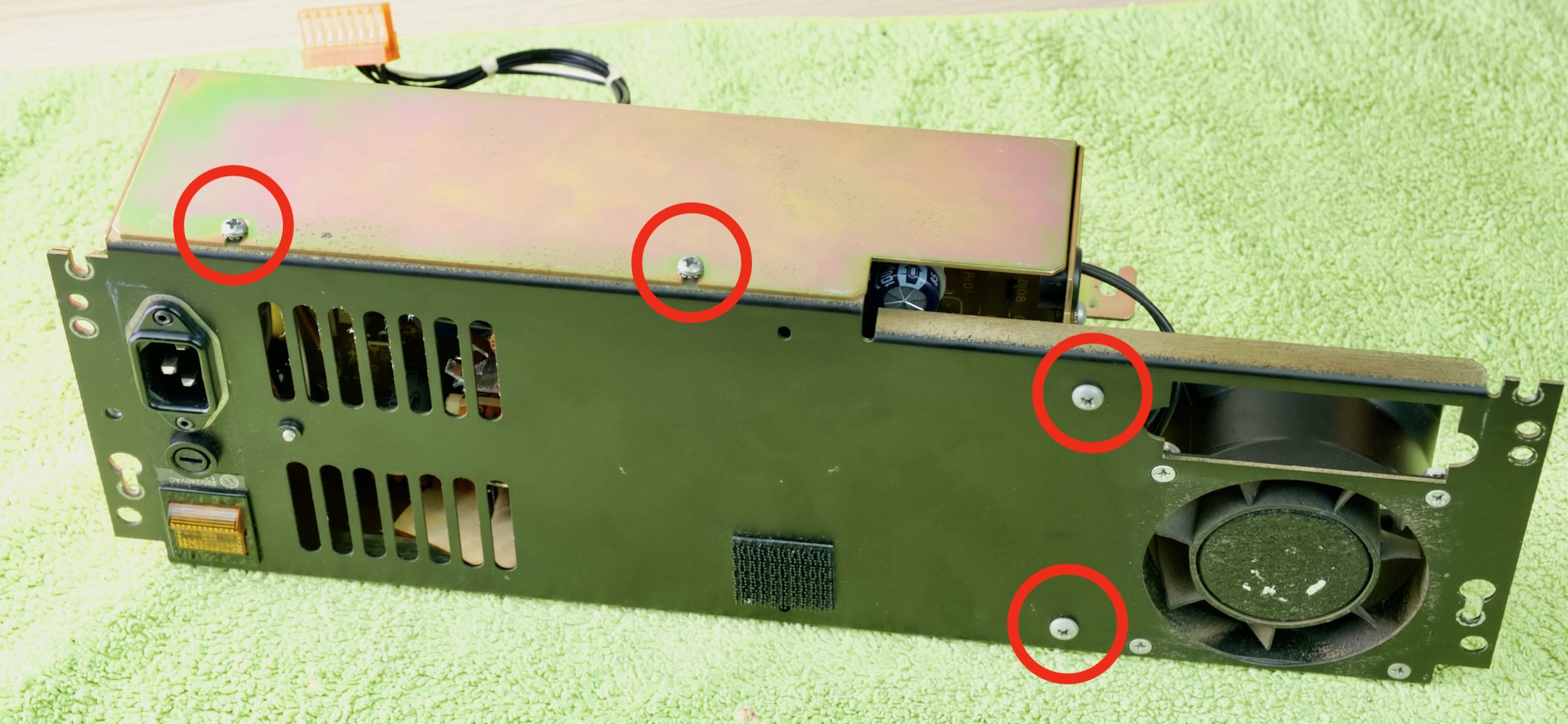
- Split the PSU in half
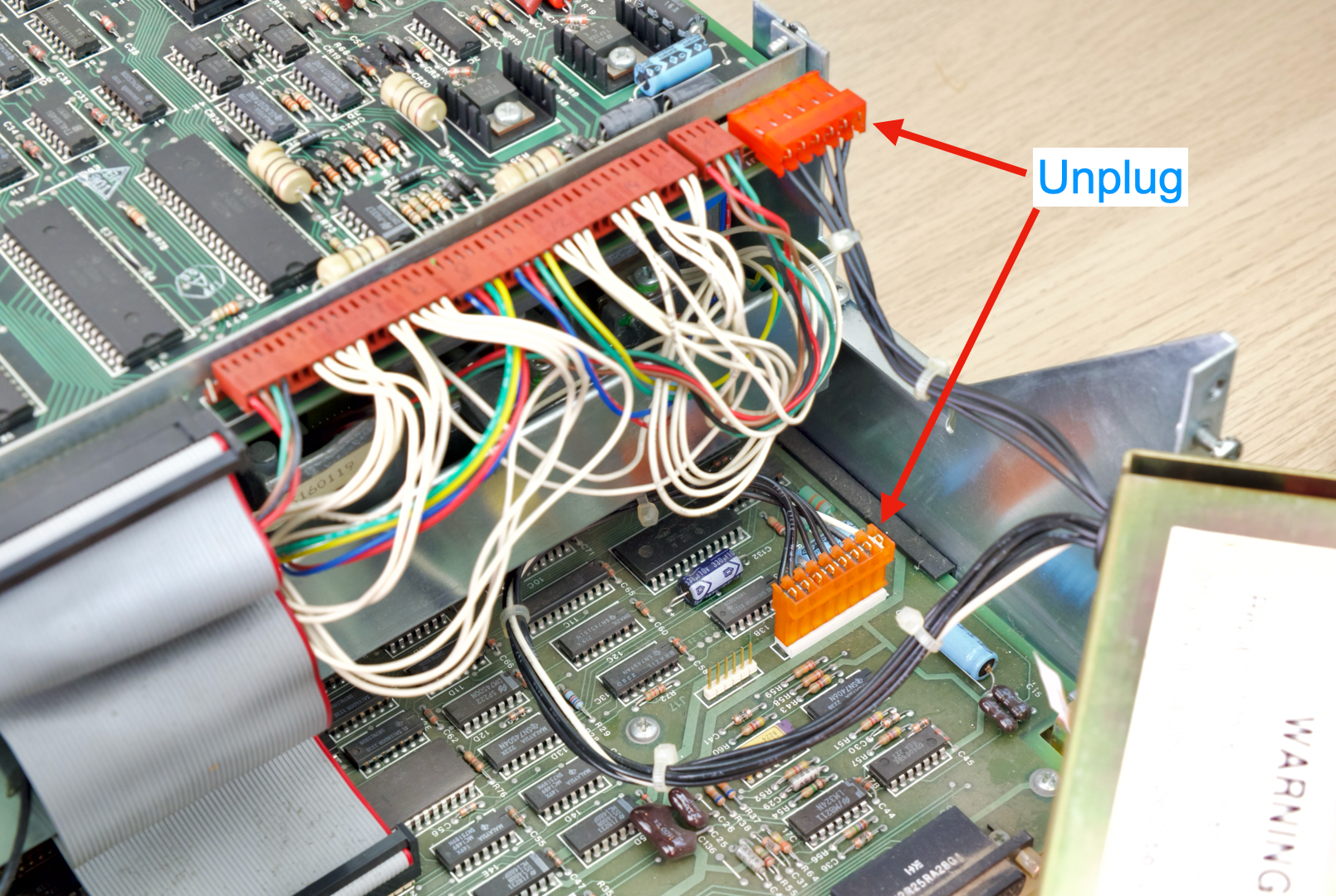
- Unplug the connectors shown
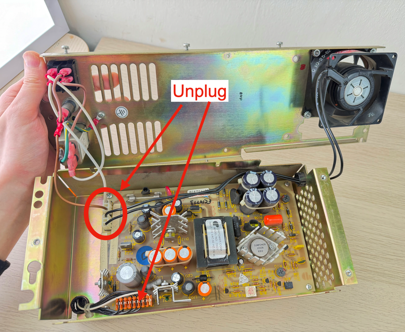
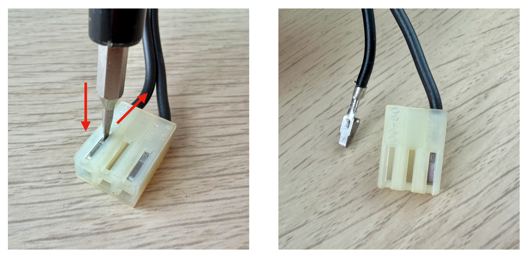
- De-pin the fan connector
- Press down on the metal tab with a thin flathead screwdriver
- AND gently pull on the cable
- It should release
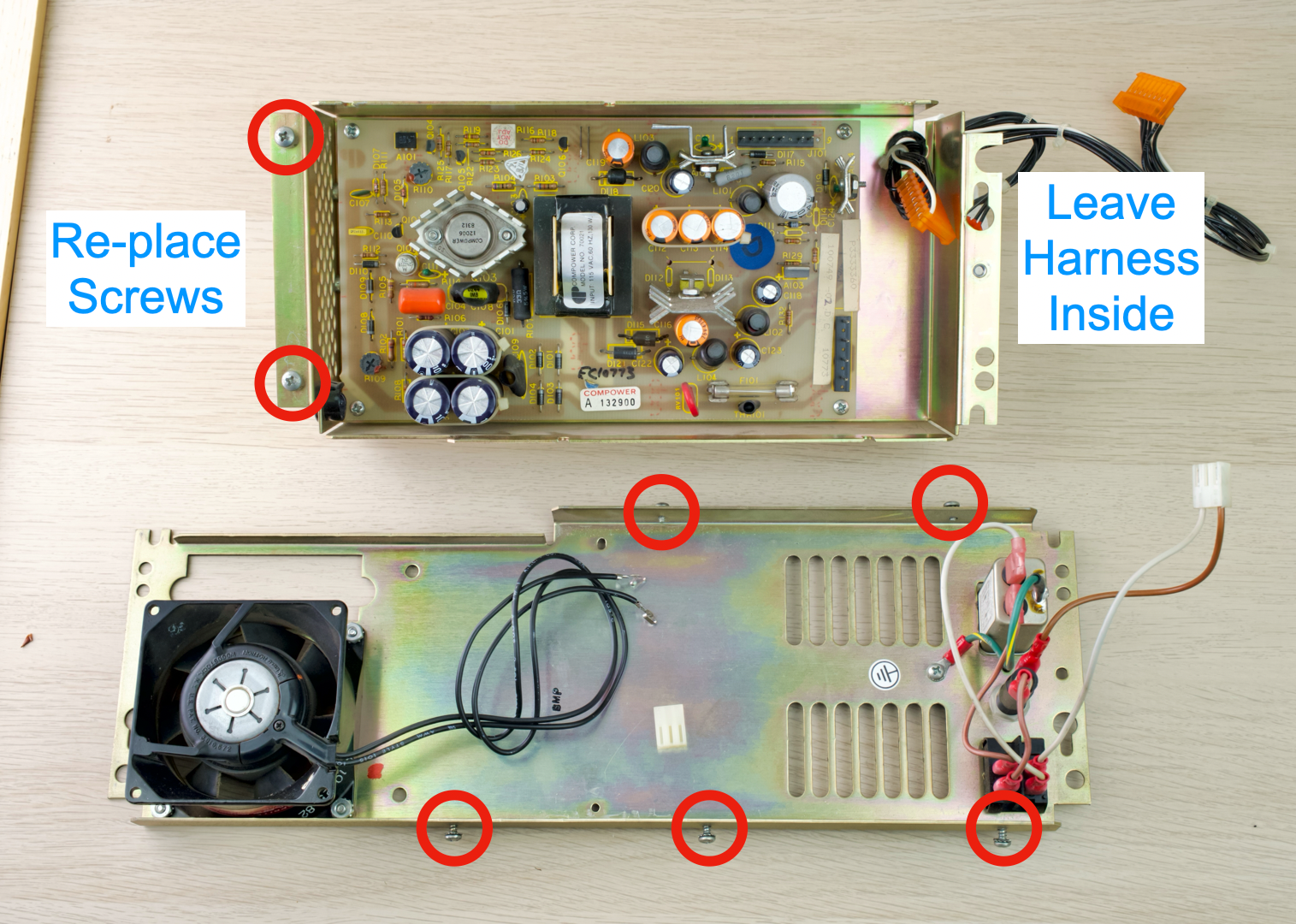
- Separate the two halves
- Reinstall screws for safekeeping
- Leave the output harness inside
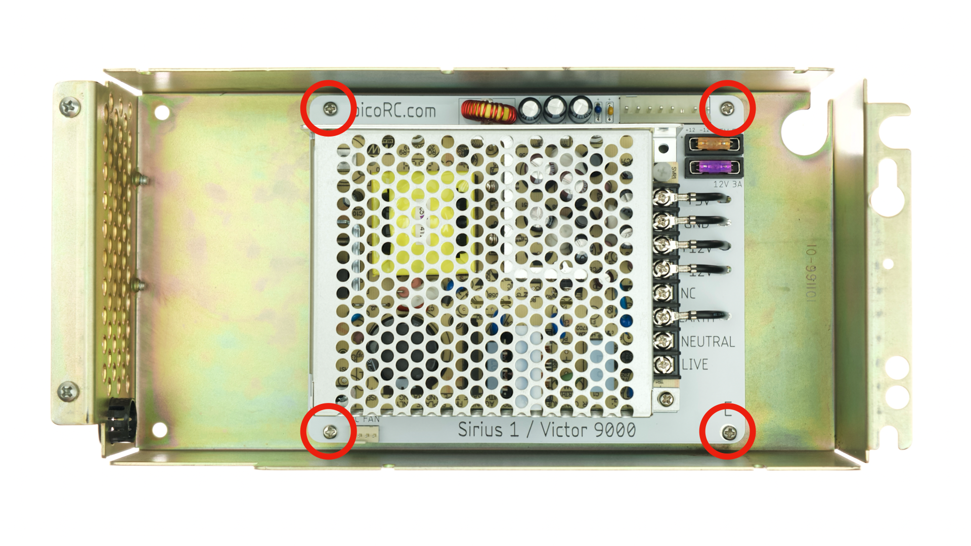
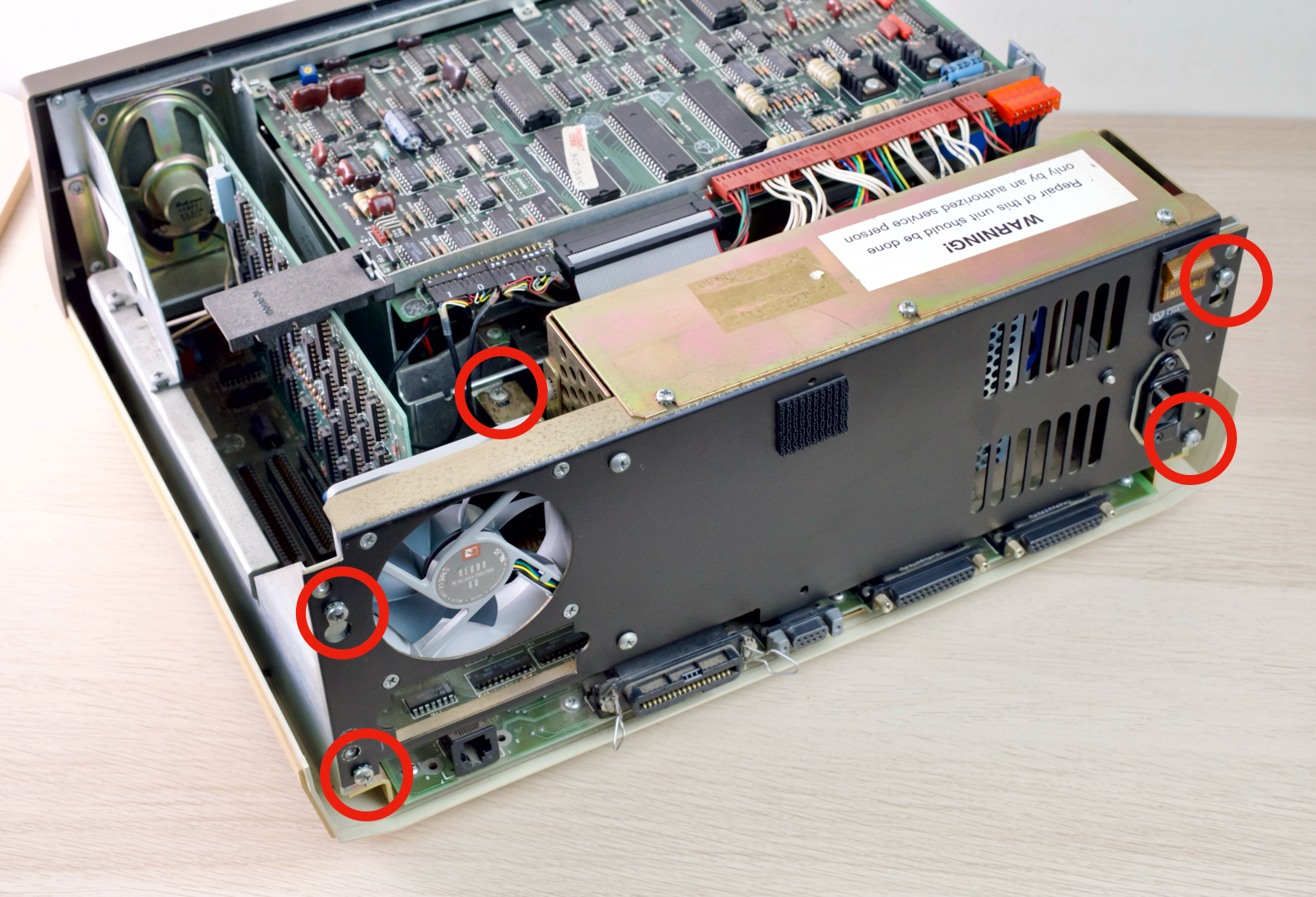
- Undo 4 screws
- Remove the circuit board
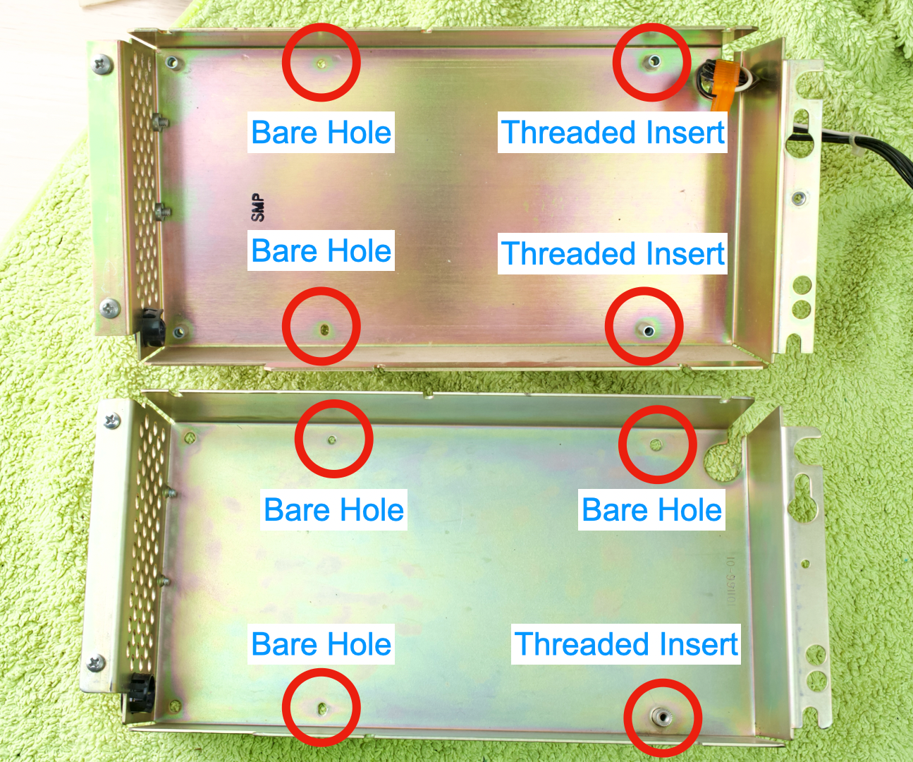
- Observe the four highlighted screw holes inside the metal case
- Some are bare holes, some have threaded inserts.
- Numbers can be different
- You may have 2 each, or 3 & 1.
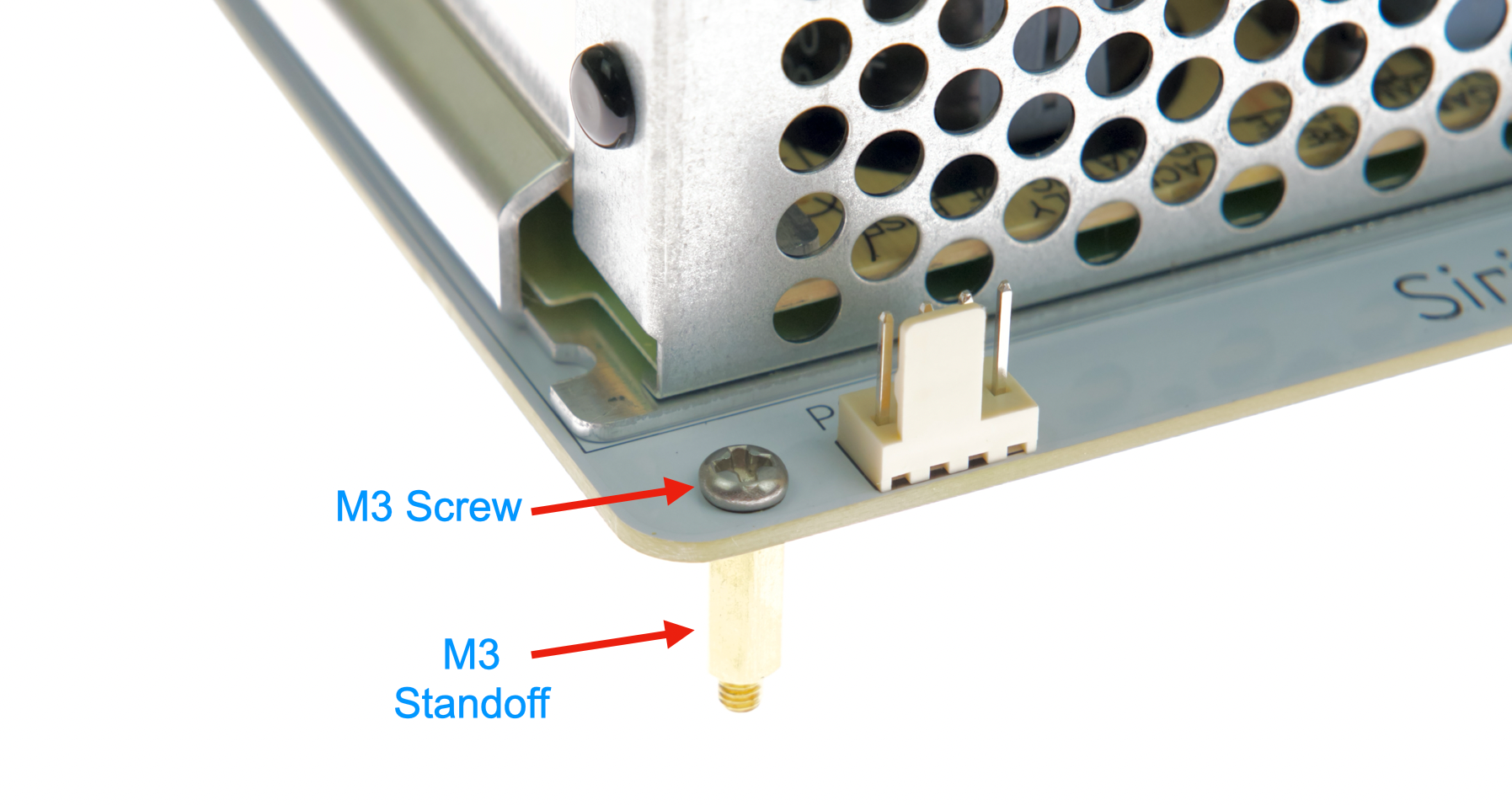
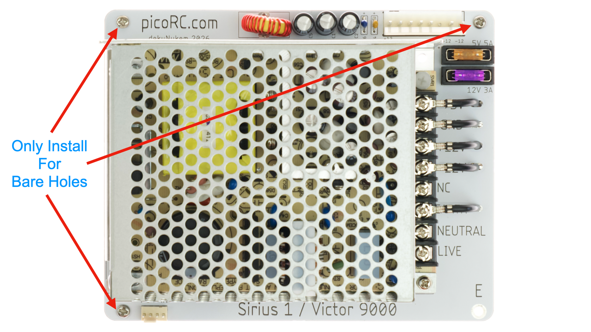
- Install M3 Screws and Standoffs on the PCB
- ONLY on corners with bare holes
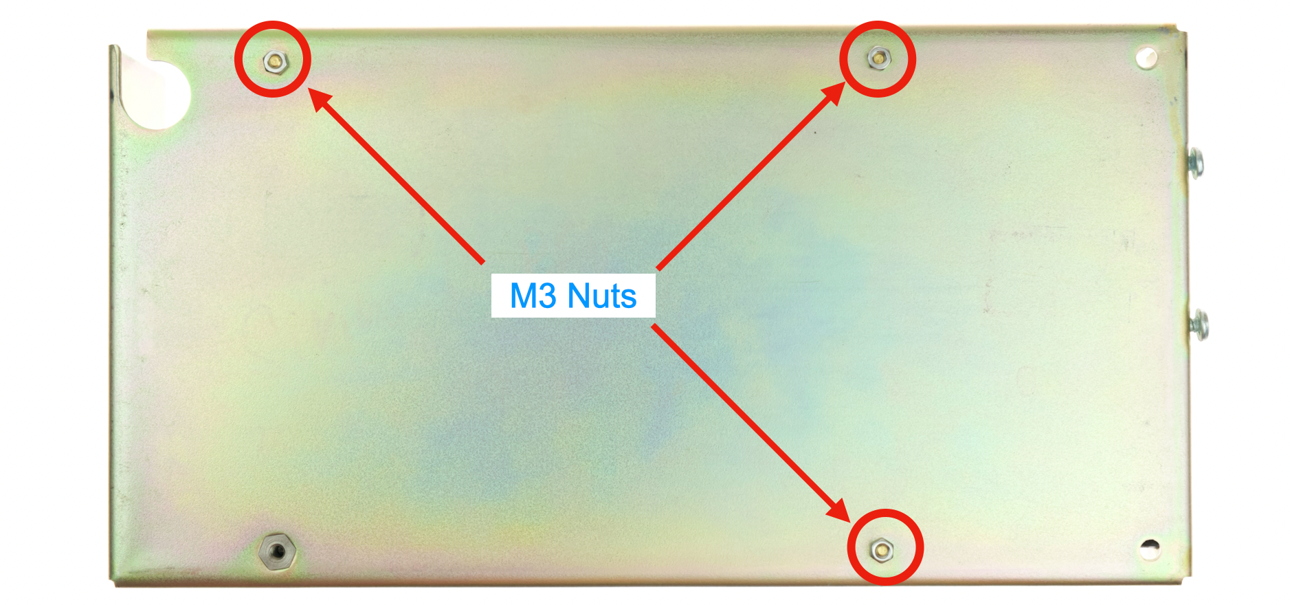
- Lower the PCB assembly into the case.
- Ensure holes line up
- You can loosen screws slightly to adjust
- Use original screws for threaded inserts
- Flip over
- Install M3 Nuts on bare holes
- We’re done with this half of the case!
- Put it away for now
- Take out the other half
- Undo the four screws to remove the fan
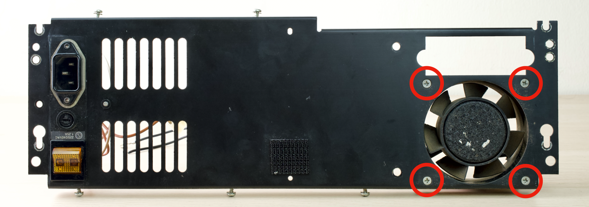
- Install the new PC Fan
- Fan should blow air OUT of case
- See arrow on the fan shroud for air direction
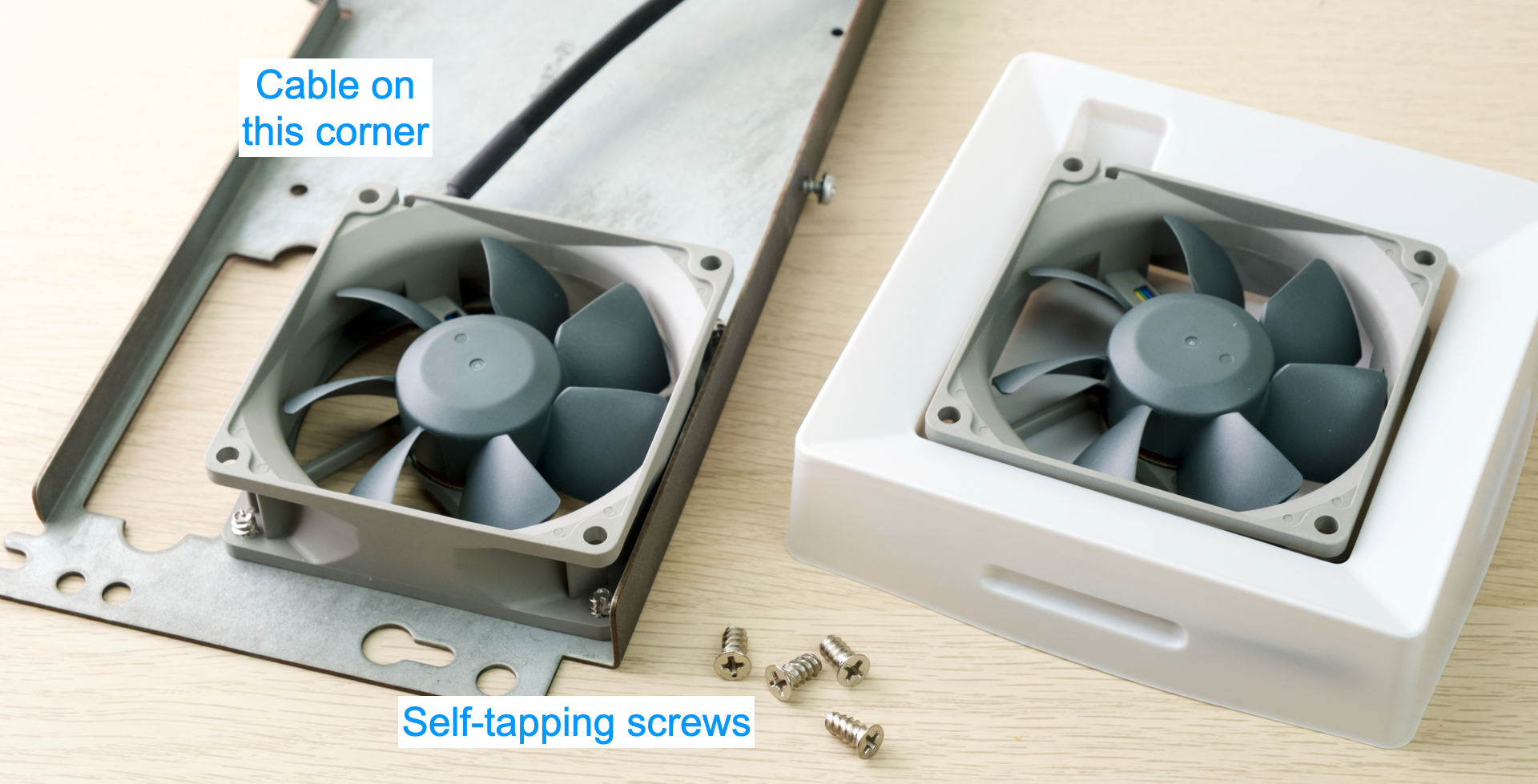
- Ensure the cable is on the corner shown
- You can use the original nuts & bolts
- But if the fan comes with self-tapping screws, you can use those too.
- Fan should blow air OUT of case
- Next up: Power Connection
- ⚠️ Involves mains voltage!
- Ensure everything is unplugged
- Pay attention to the instructions!
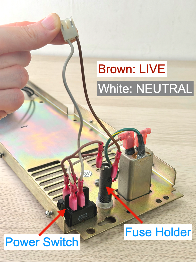
- Look at the connector that plugs into the old PSU
- It should have two wires.
- Brown is LIVE
- Comes out of fuse holder
- White is Neutral
- Comes out of the power switch
- Remember where they go!
- Take photos!
- Unplug the LIVE wire from the Fuse Holder
- Use a pair of pliers
- Grab the NECK
- Wiggle side-to-side and pull
- DO NOT pull on the wire itself!
- Plug the new BROWN wire into the same terminal.
- All the way in
- Ensure the protective cover is in place
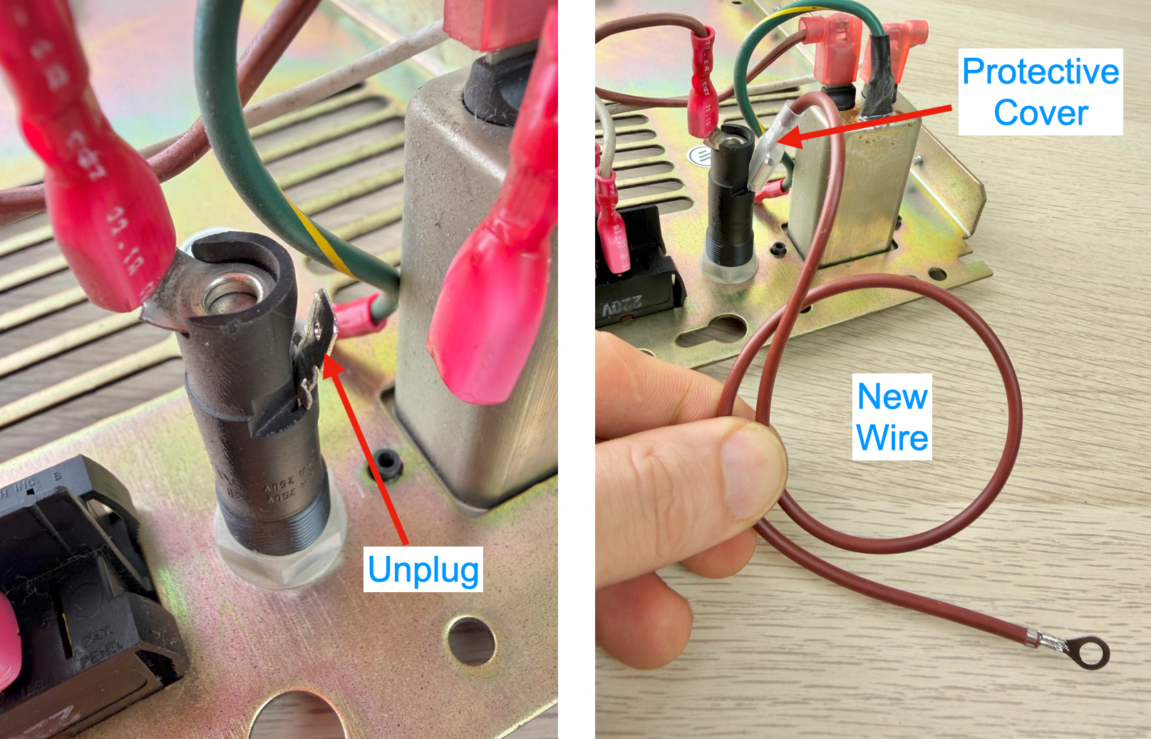
- Unplug the old white Neutral wire
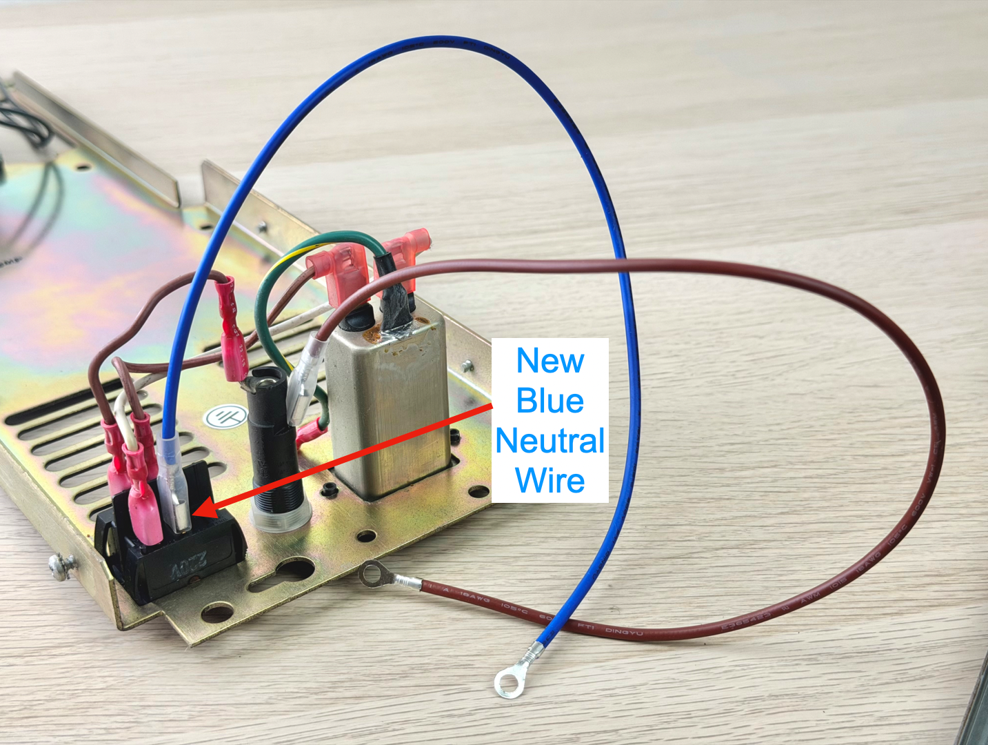
- Plug in the new blue Neutral wire
- Same precautions
- On the home stretch now!
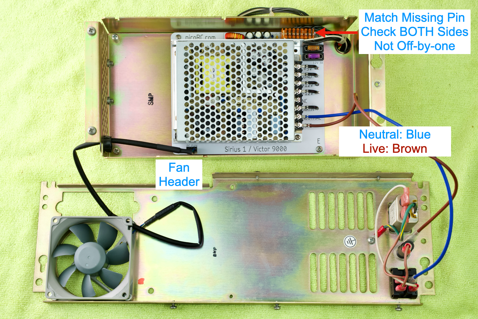
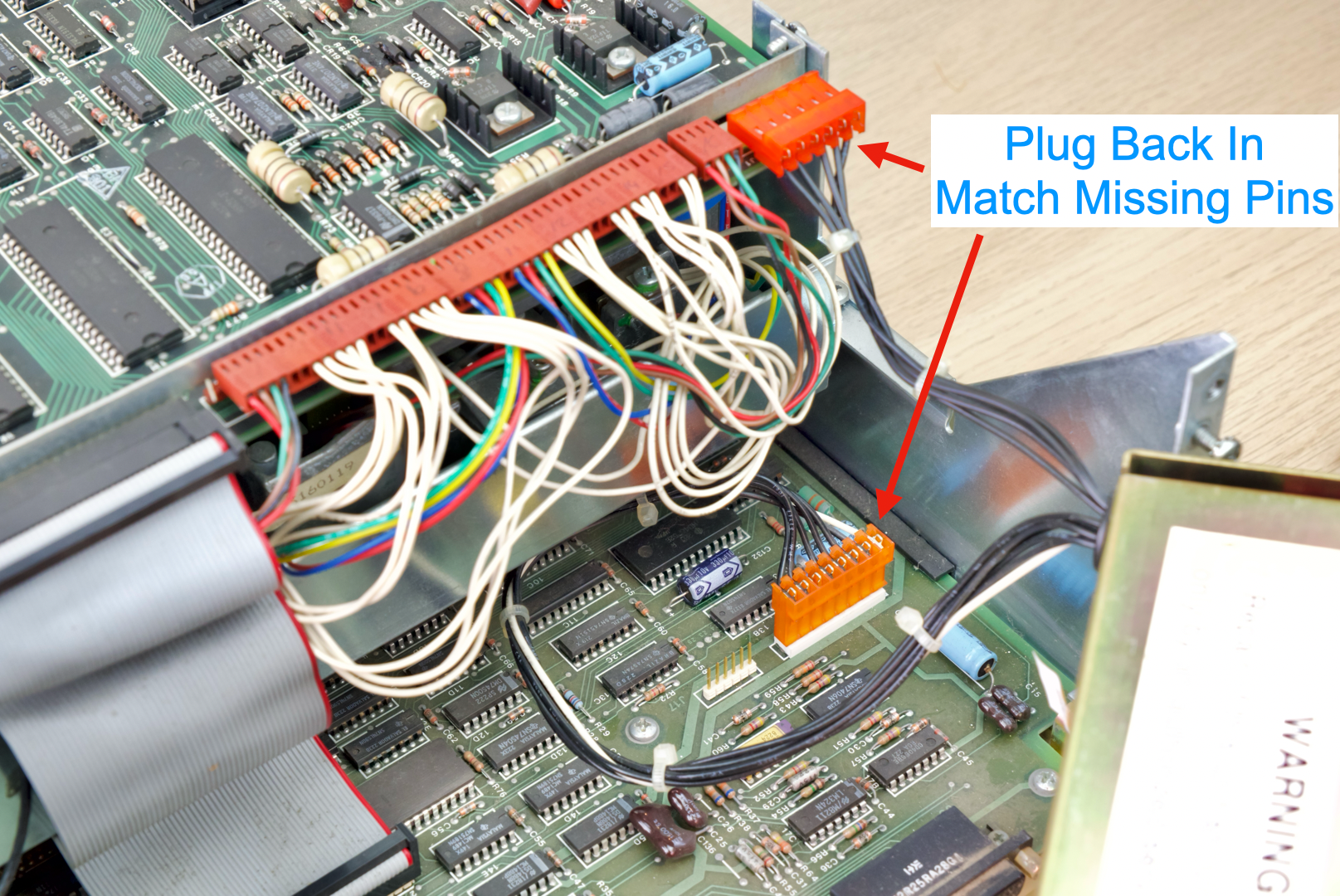
- Plug the output harness into the PCB
- Match the missing pin
- Check BOTH ends to ensure it’s not off-by-one.
- Insert 4-pin fan cable
- Should fit through the grommet, barely.
- Plug into fan header
- Install mains wires on MeanWell PSU
- Neutral: Blue
- Live: Brown
- Double check all terminal connections
- Should be tight
- No rattles
- Put the two halves back together
- Remove hand-tight temp screws
- Tuck wires, ensure nothing is pinched.
- Redo the screws
Take a breath and turn it on by itself!
Good signs include:
- Not blowing up
- Fan spins
- Power light is on
If so, congrats!
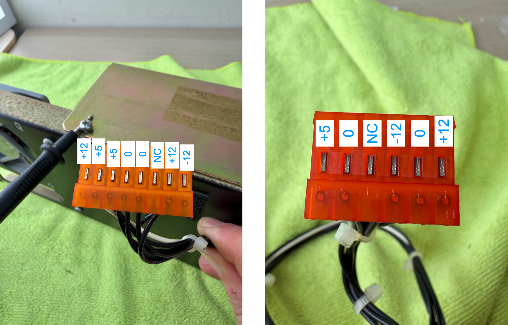
- Before reinstalling, double check voltage
- Use a multimeter
- Black probe on metal case (Use a screw to hold in place)
- Touch red probe on each metal contact
- Make sure voltage rail matches
- ±5% is fine
- NC = Not connected, no wires.
- If values are completely wrong, make sure you didn’t plug in the harness backwards or off-by-one.
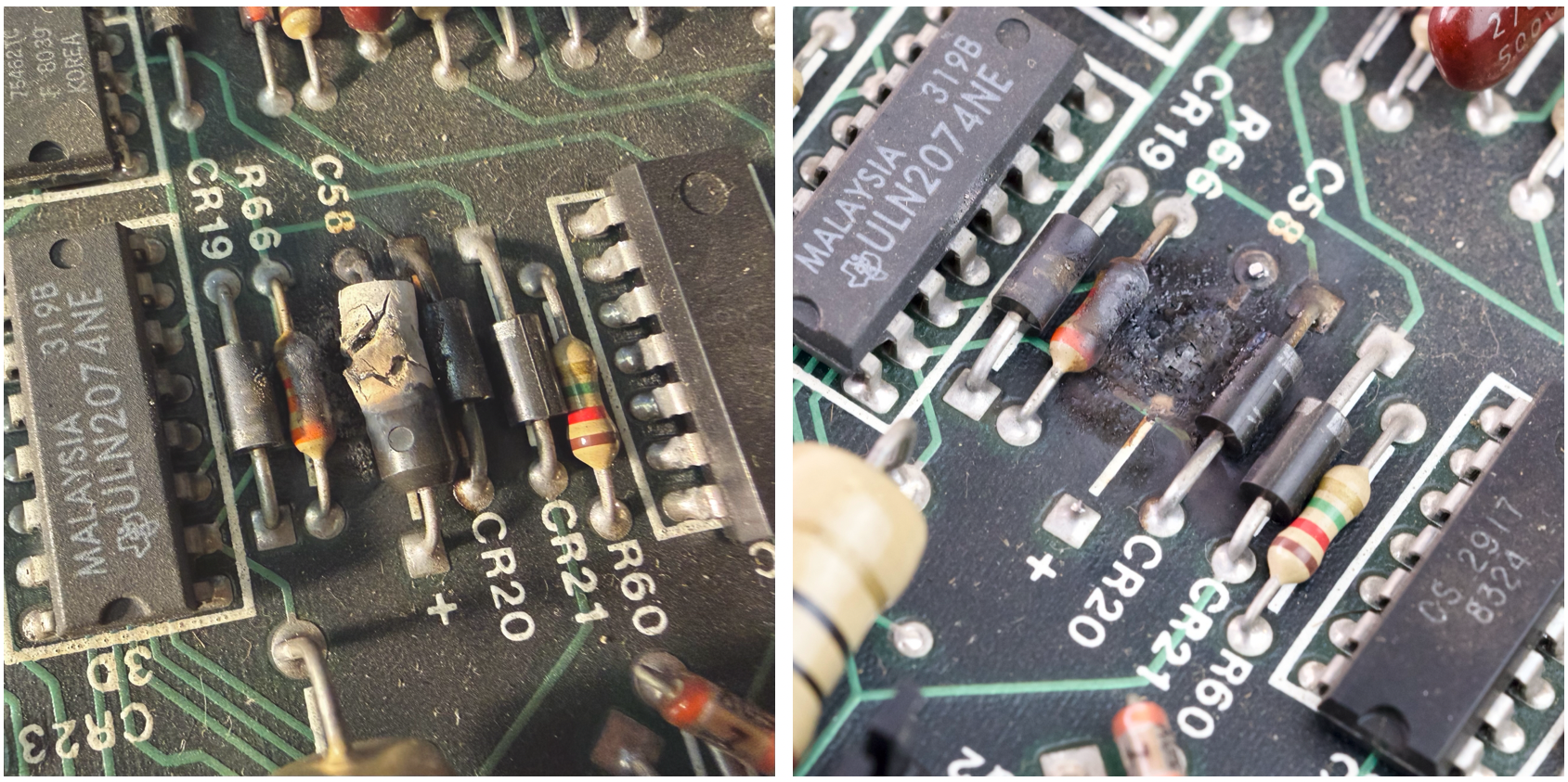
💥 Exploding Caps Alert
There are a few Tantalum Capacitors on the floppy controller PCB.
As they age, they often fail short and explode or trip the protection circuit.
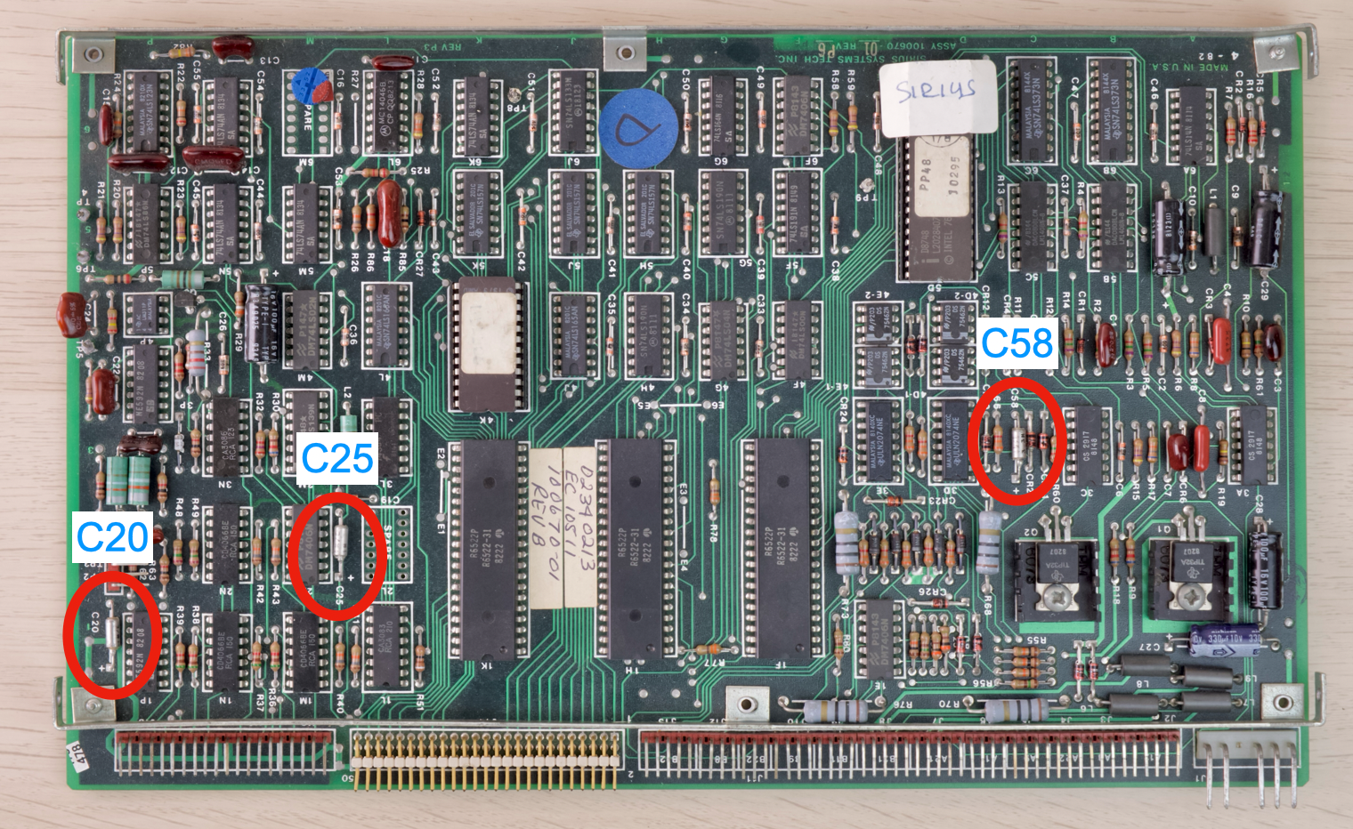
How they look like:
Check for Shorted Caps
- Multimeter, continuity mode, touch both ends of the cap.
- If the meter shows a dead short (less than 10 ohm), then most likely the cap has shorted.
- You can just cut it off, no need to replace.
- If no short, you can leave it or cut it.
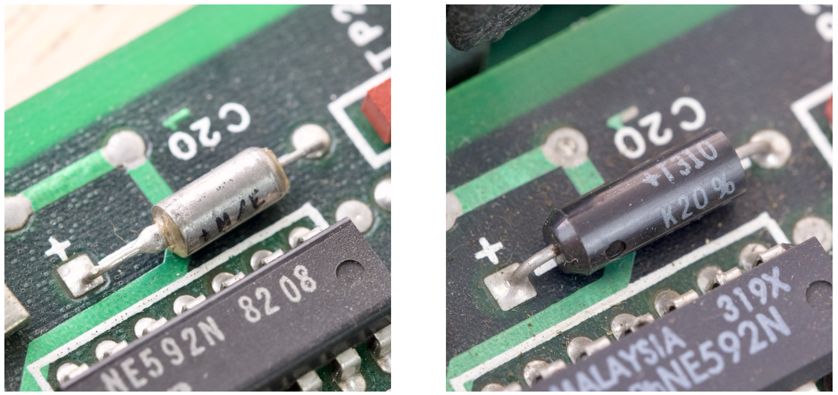
How they look after the big woopsie:
Anyway, now you’re aware, we can continue putting it back together.
- Reconnect the power connectors
- Match missing pins
- Remove finger-tight temp screws
- Reinstall PSU
First Power-On
- Use eye-protection
- If a cap explodes, cut it off.
- If fuses blows or PSU goes into protection, check for shorted caps on 12V rail again.
Hopefully it works!
While you’re in there, might worth giving the floppy drive a service and clean out the dust.
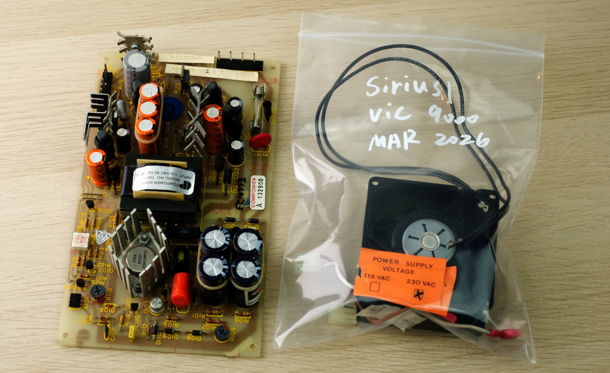
Keep the Original Parts!
- DO NOT throw anything away!
- Put all the removed parts in a bag or box
- Clearly label and date for future reference
Reassemble fully and enjoy!
Questions or Comments?
Feel free to ask in official Discord Chatroom, raise a Github issue, or email dekunukem gmail.com!