PicoRC
PicoPSU Adaptor for IBM Portable Personal Computer 5155
| Purchase Link | Official Discord | Table of Contents |
This adaptor lets you use Pico ATX PSU on the IBM 5155 Portable Personal Computer.
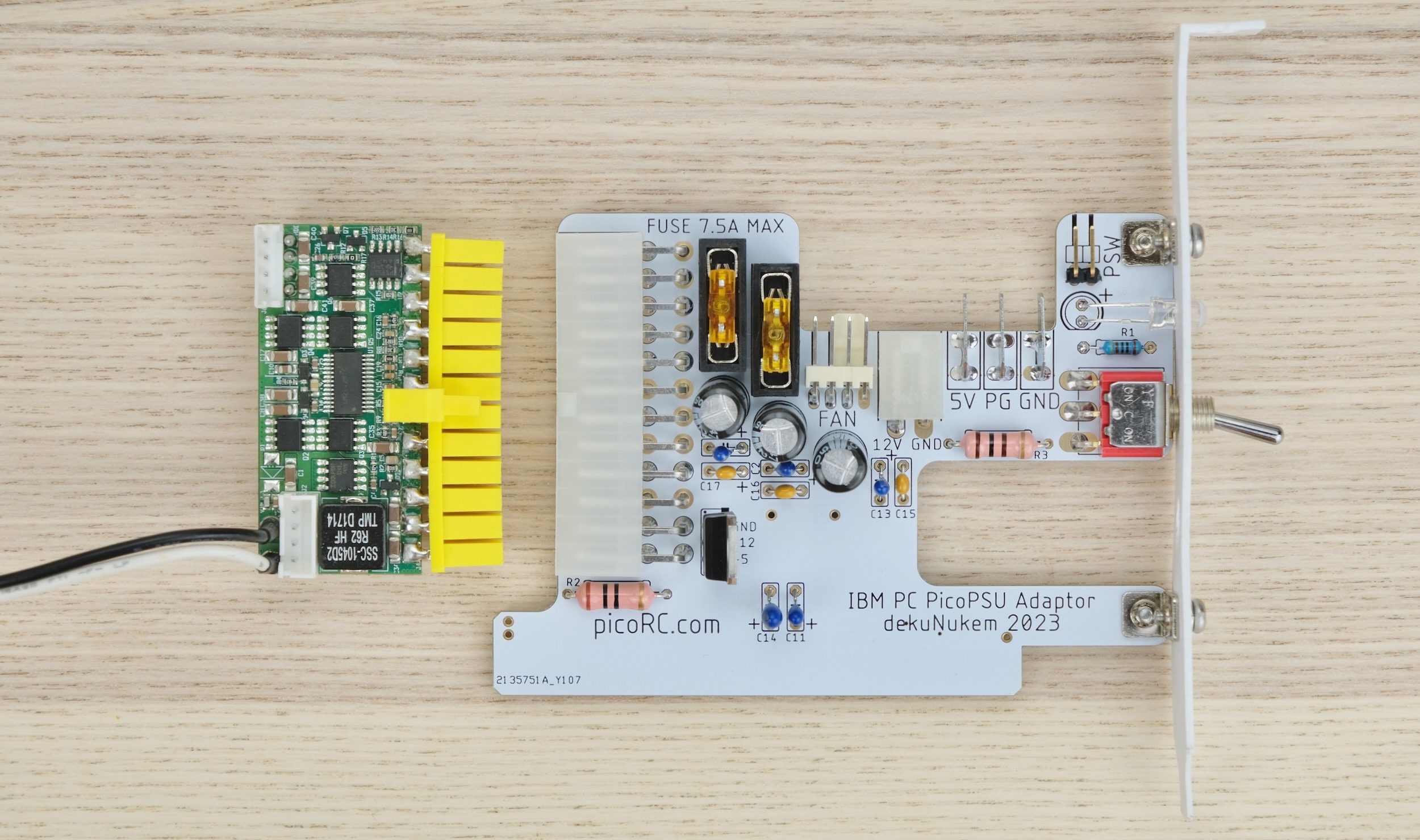
The PSU-in-a-Card replaces the original PSU, and uses very common 12V power brick instead.
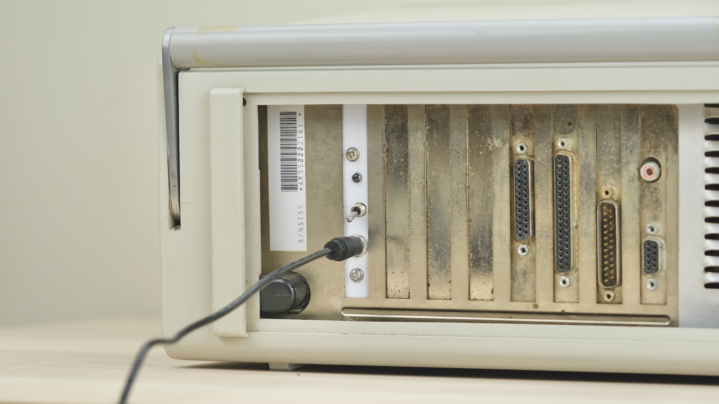
Features
-
Non-destructive
-
PC fan header
-
Built-in power switch
-
Also supports the Big Red Switch™
Also Works on Regular IBM PC Compatibles!
Click me to see its own guide!
Get One / Other Stuff
Also available for Regular PC, Compact Macintosh, Apple II/IIGS, Osborne 1, Apricot PC, BBC Micro, and more!
For more general-purpose diagnostics and retrofitting, check out the full-fat ATX4VC!
Table of Contents
Getting a Pico PSU
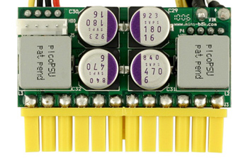
PicoPSUs are tiny ATX power supplies for small PCs, but are perfect for retro computers as well.
-
The cheapest 80W one should be plenty for the floppy-only model.
-
The 160W variant is recommended if using many expansion cards and/or the spinning hard drive.
-
Avoid generic clones. They over-rate and are of low quality.
-
A 12V DC power brick with center positive 5.5x2.5mm barrel jack is needed.
-
They are very popular and you might already have one. Make sure it has enough wattage.
Kit Assembly
- 🚨🚨🚨🚨 This guide is for IBM 5155 PORTABLE PC, CLICK ME FOR GENERIC IBM PC COMPATIBLES 🚨🚨🚨🚨
- 🚨🚨🚨🚨 This guide is for IBM 5155 PORTABLE PC, CLICK ME FOR GENERIC IBM PC COMPATIBLES 🚨🚨🚨🚨
- 🚨🚨🚨🚨 This guide is for IBM 5155 PORTABLE PC, CLICK ME FOR GENERIC IBM PC COMPATIBLES 🚨🚨🚨🚨
- 🚨🚨🚨🚨 This guide is for IBM 5155 PORTABLE PC, CLICK ME FOR GENERIC IBM PC COMPATIBLES 🚨🚨🚨🚨
DON’T START YET!!! Keep reading :)
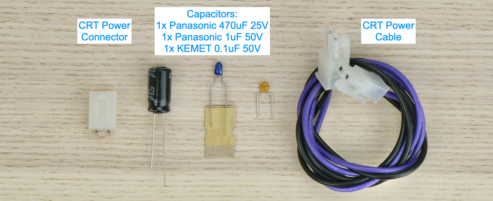
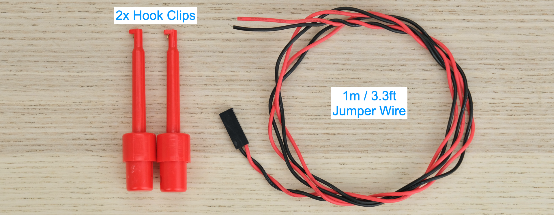
Observe the parts:

Soldering Notes
Nothing too tricky in this kit, all basic through-hole stuff.
If this is your first time, a few tips:
-
Make sure your soldering iron has proper temperature control. Try your local makerspace or university lab.
-
Use leaded solder and plenty of flux, temperature around 320C / 600F.
-
This video covers the basics pretty well.
Assembly
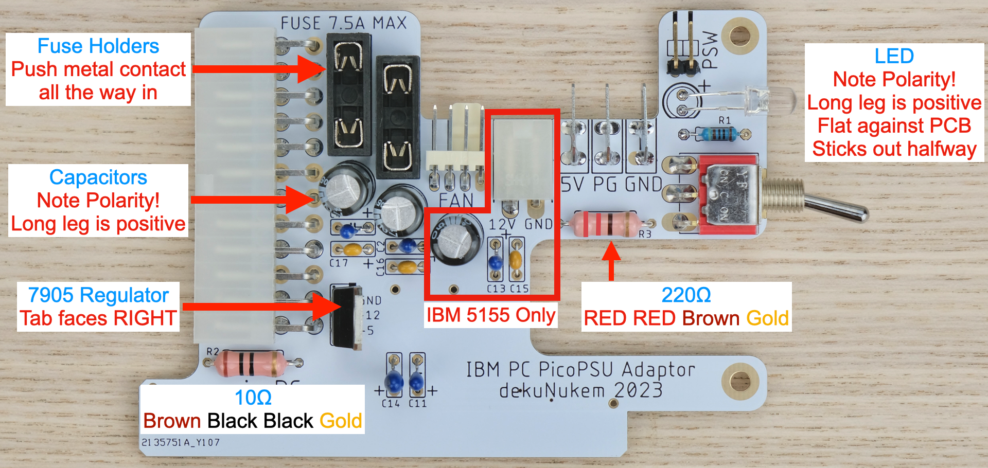
Solder the components as shown below:
-
Double check capacitor polarity!
-
Black electrolytic caps: White stripe is NEGATIVE.
-
Blue Tantalum caps: White stripe is POSITIVE.
-
Yellow ceramic caps: No polarity.
Cleaning
This is optional, but I like to clean off the flux with 90%+ isopropyl alcohol.
Submerge and scrub with a toothbrush.
Make sure it is completely dry before proceeding.
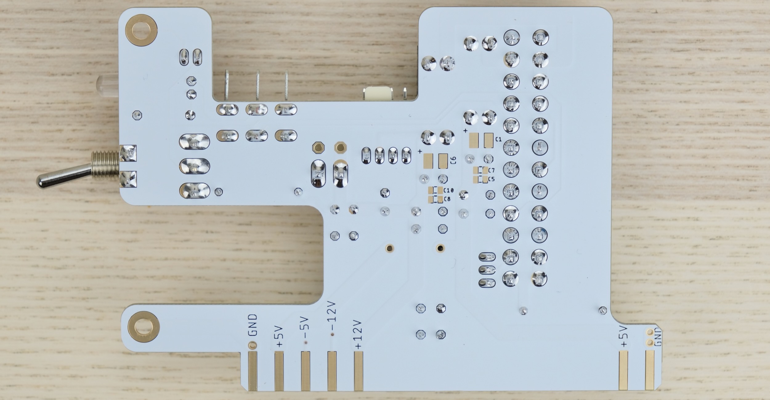
Inspection
-
Compare with the photo and notes above. Make sure everything is in correct orientation.
-
Solder joints should be shiny and smooth. If you see spikes, put on more flux and melt it again.
-
There must be no solder bridges. If any, put on flux and melt it to remove.
Bracket
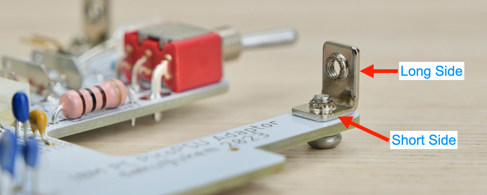
Install the metal bracket.
The shorter side should be touching the PCB.
Secure with M3 screws from the bottom.
Then install the ISA bracket, secure with two more M3 screws.

Installation
Install two 5A fuses.
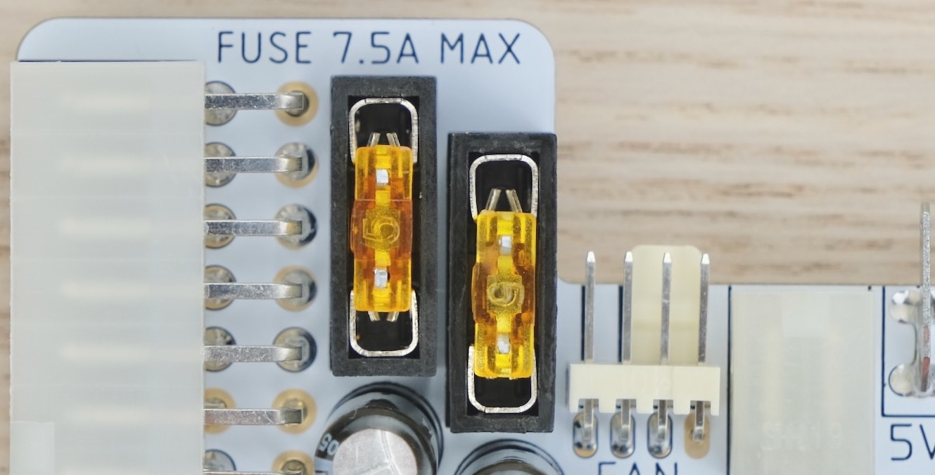
Use a multimeter to check for dead shorts between each power rail and GND:

If all good, plug in PicoPSU, and flip the switch.

The LED should light up. The LED is wired to the POWER_GOOD signal, so there might be a slight delay.
Measure the voltage of each rail, make sure they are correct.
Undo the locking ring on the barrel jack.
Insert through the hole on the bracket.
Tighten the ring from the other side. Use 10mm socket.

Insert the power cables into the terminal blades.
-
Match the colours! (RED: 5V ORANGE: PowerGood BLACK: GND) -
Ensure the connectors are all the way in.
- Ensure the insulating sleeves are in place.
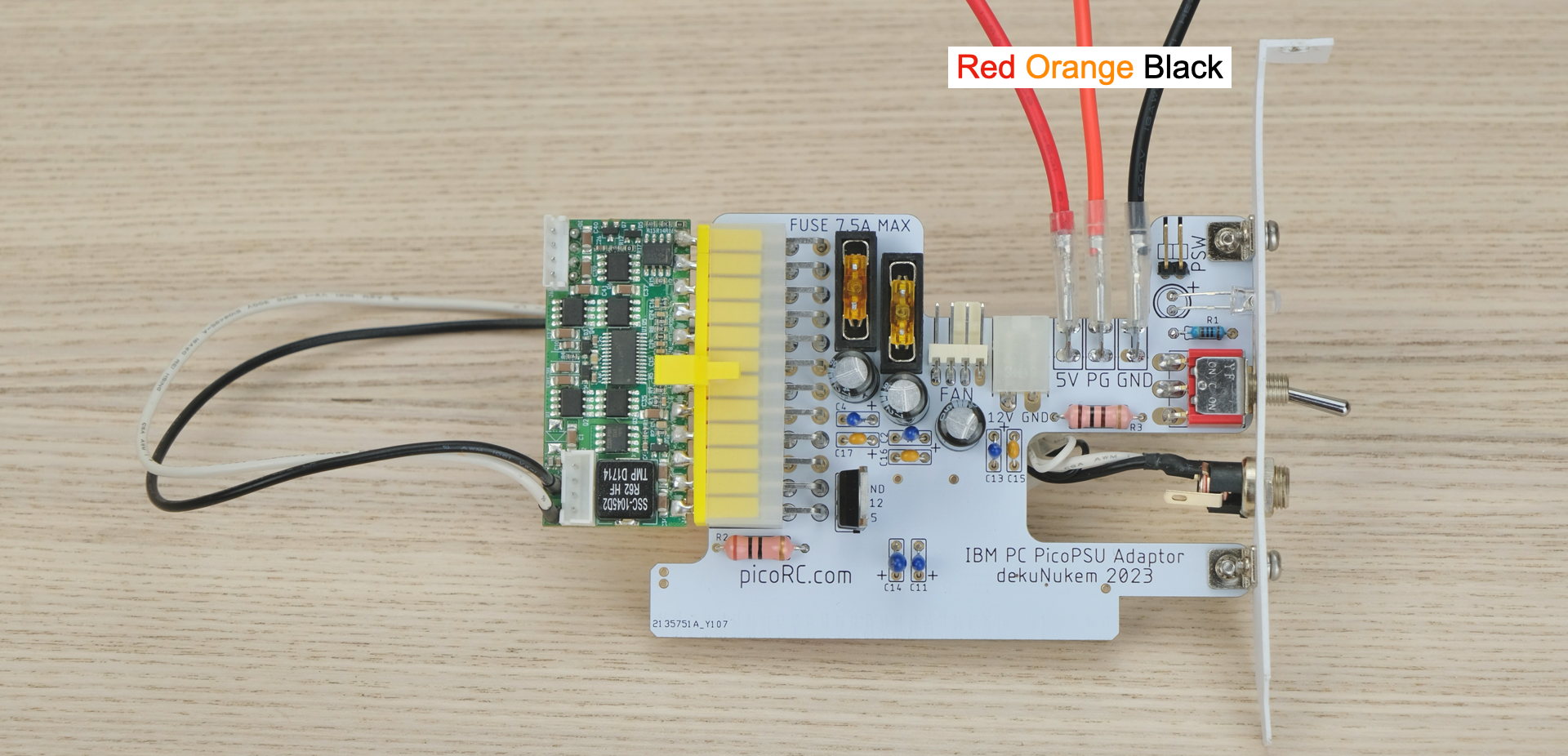
Now we’re ready to install!
- 🚨🚨🚨🚨 This guide is for IBM 5155 PORTABLE PC, CLICK ME FOR GENERIC IBM PC COMPATIBLES 🚨🚨🚨🚨
- 🚨🚨🚨🚨 This guide is for IBM 5155 PORTABLE PC, CLICK ME FOR GENERIC IBM PC COMPATIBLES 🚨🚨🚨🚨
- 🚨🚨🚨🚨 This guide is for IBM 5155 PORTABLE PC, CLICK ME FOR GENERIC IBM PC COMPATIBLES 🚨🚨🚨🚨
- 🚨🚨🚨🚨 This guide is for IBM 5155 PORTABLE PC, CLICK ME FOR GENERIC IBM PC COMPATIBLES 🚨🚨🚨🚨
⚠️⚠️ Insert the blanking plug into the power socket. ⚠️⚠️
This prevents the old faulty/unknown PSU from being accidentally energized.

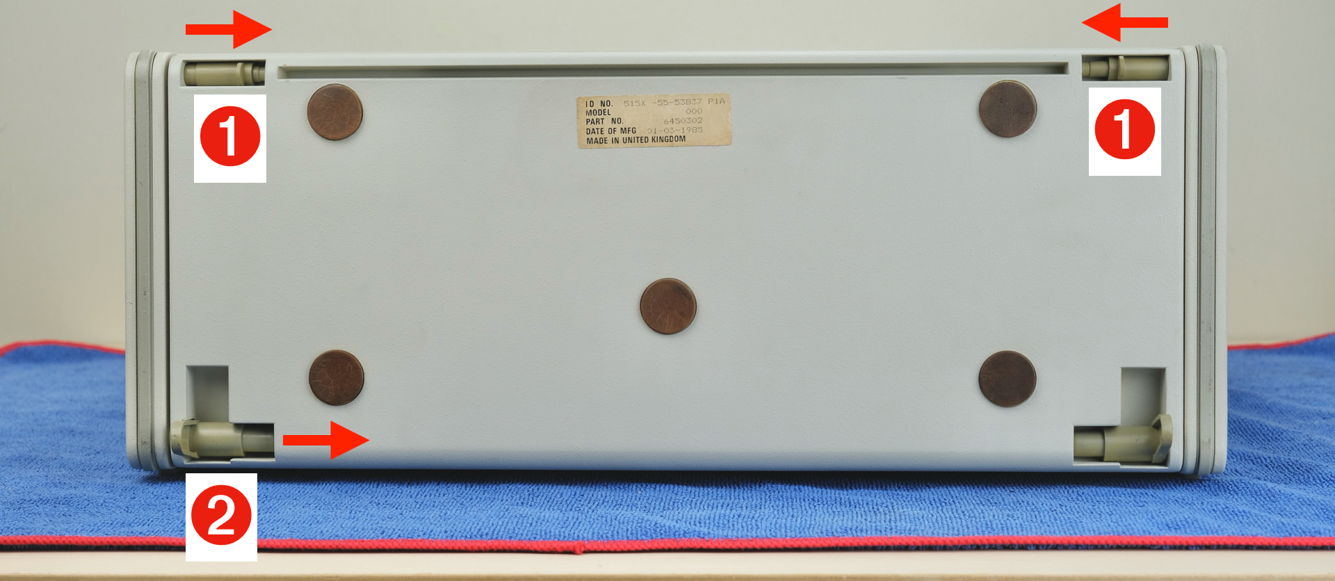
(1) Unlatch the keyboard.
(2) Release, unplug, and remove the keyboard.
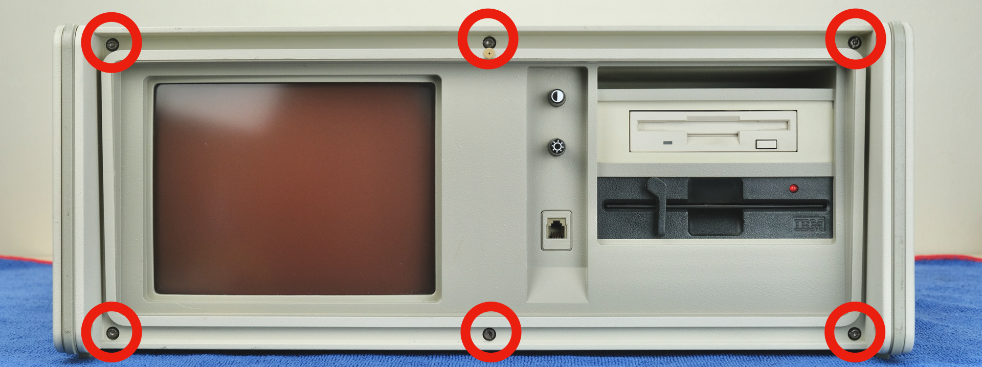
Undo six screws on the face plate.
Slide the outer case backwards to remove.
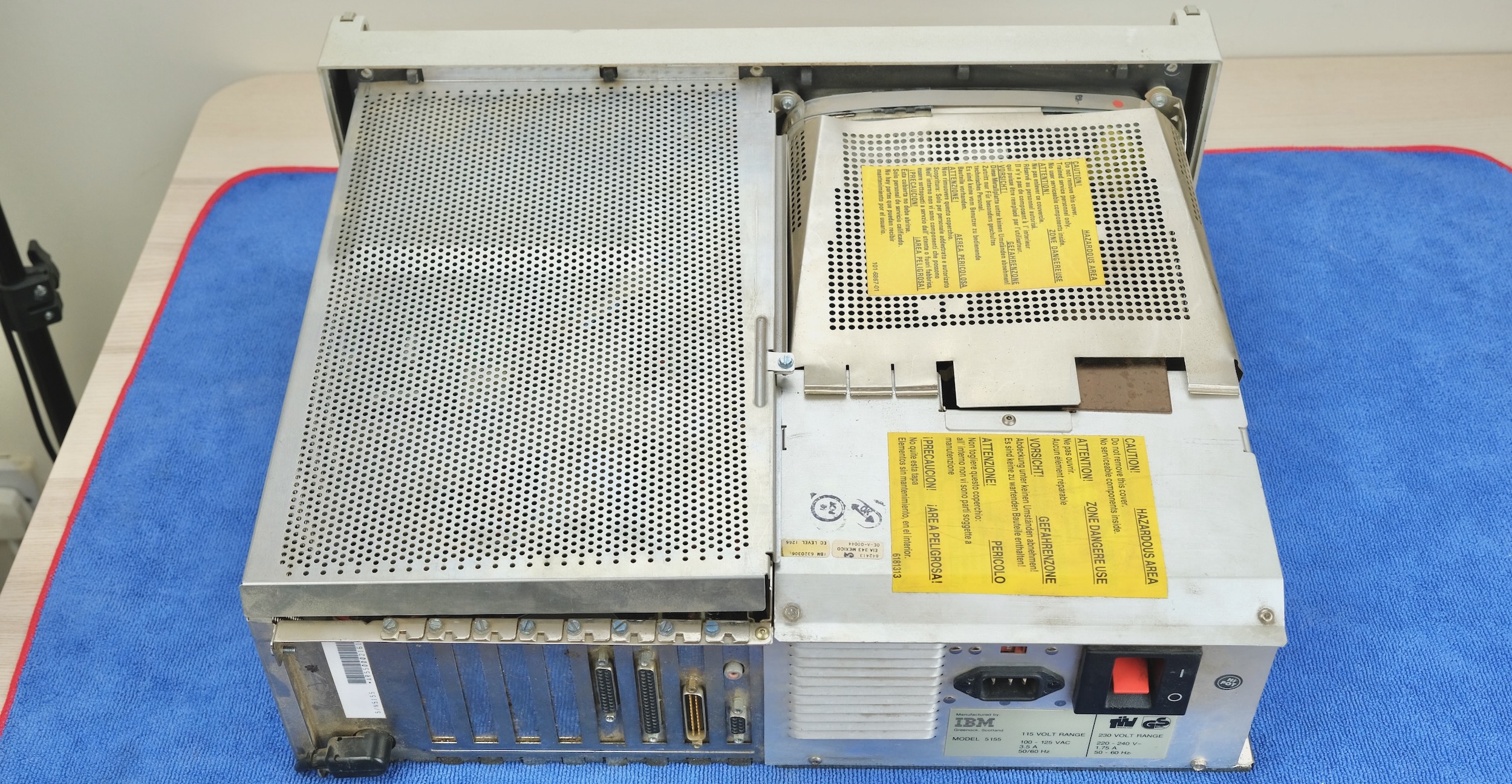
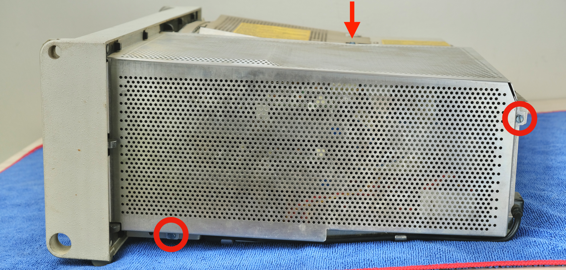
Undo three screws and remove the RF cage.
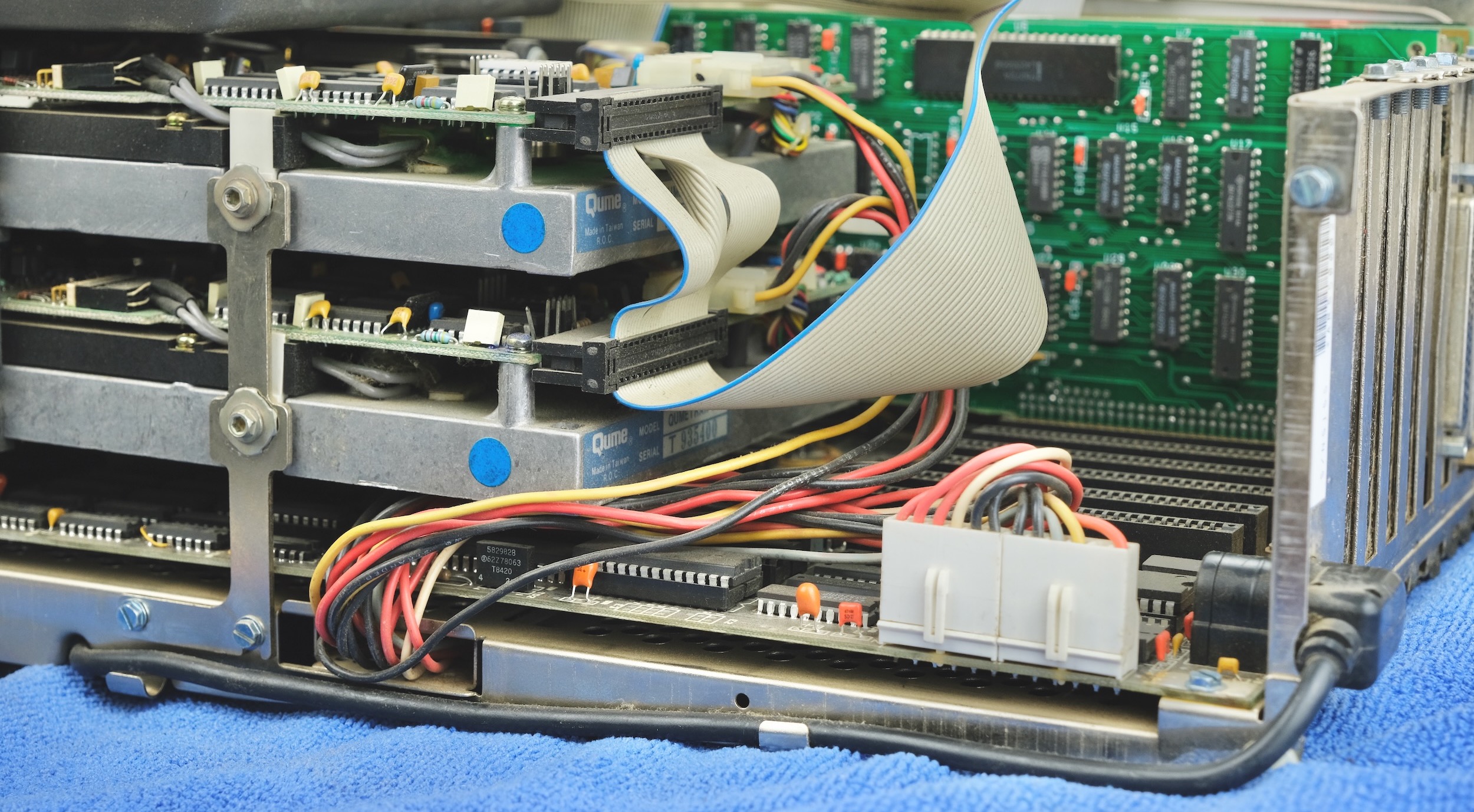
Unplug the floppy cable and all power connectors to free up some space.
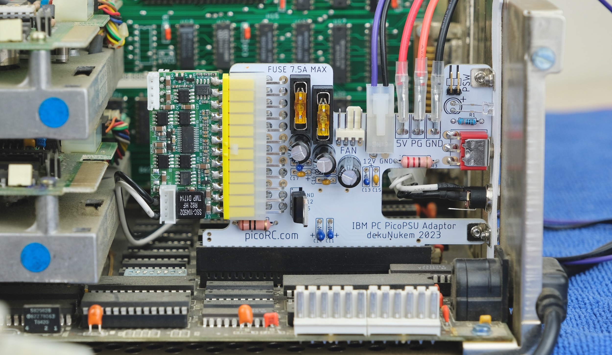
Plug the adaptor into an ISA slot.
The outmost one is recommended.
Secure with screw.
Insert a flat-blade screwdriver into the blade receptacle.
Expand the gap slightly so it goes in easier.
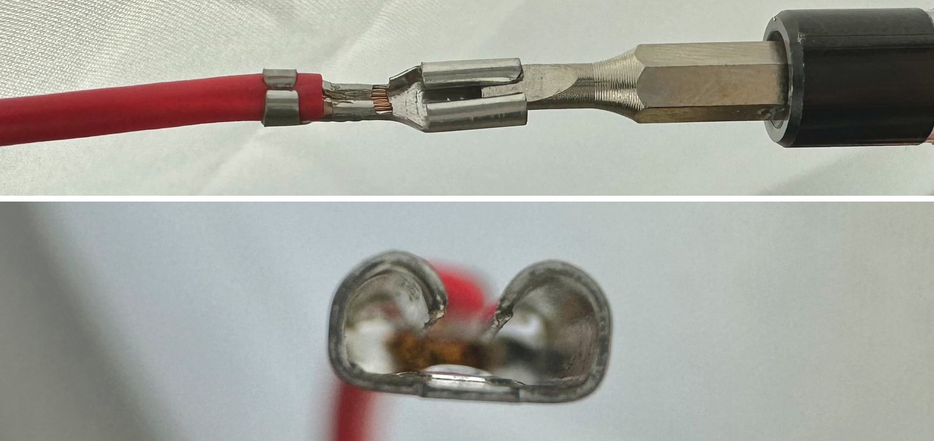
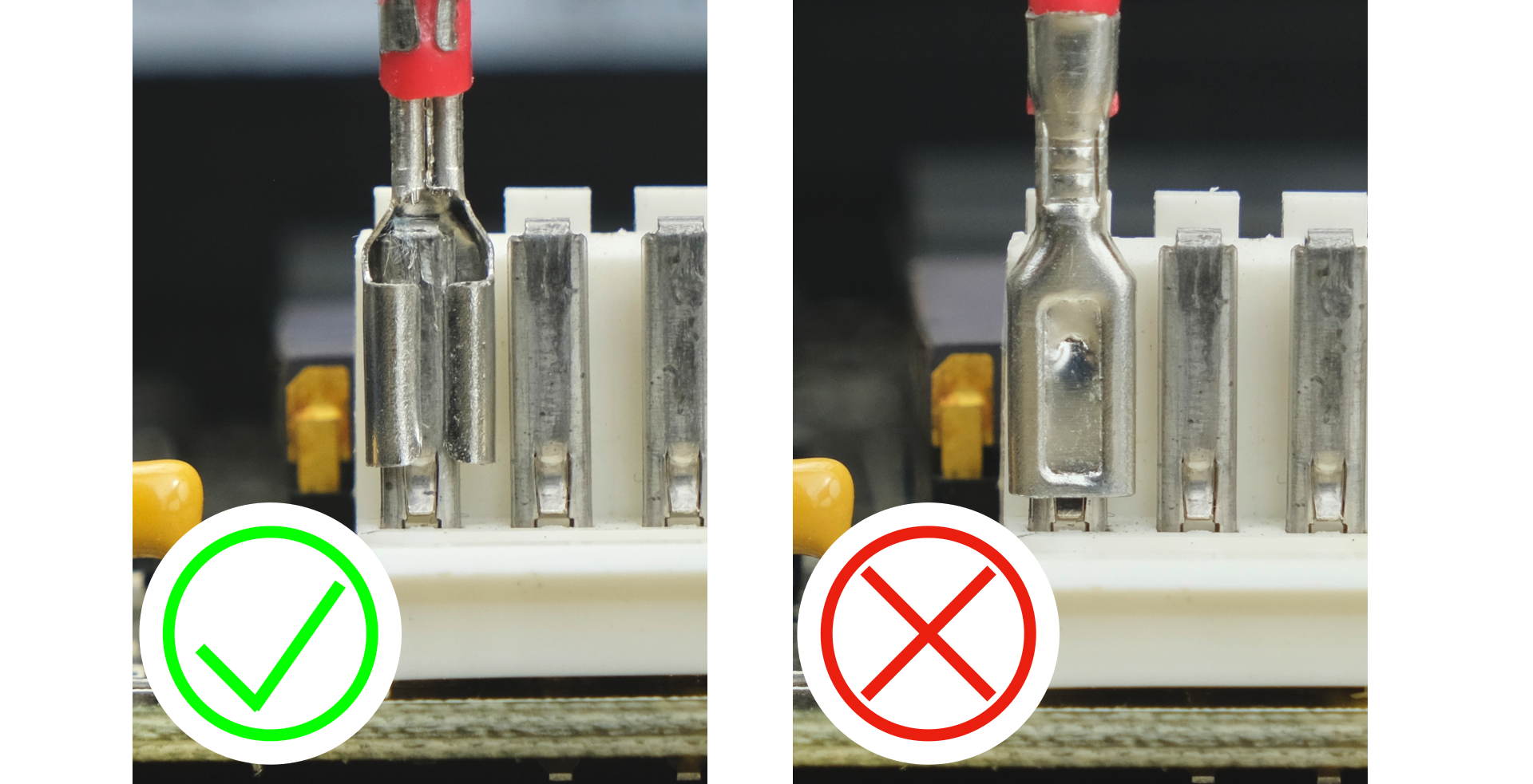
Time to insert the power cables.
Push straight down, make sure lobe side faces outwards.
Don’t force if there is significant resistance, make the gap bigger and try again.
Of course, it shouldn’t be too loose either.
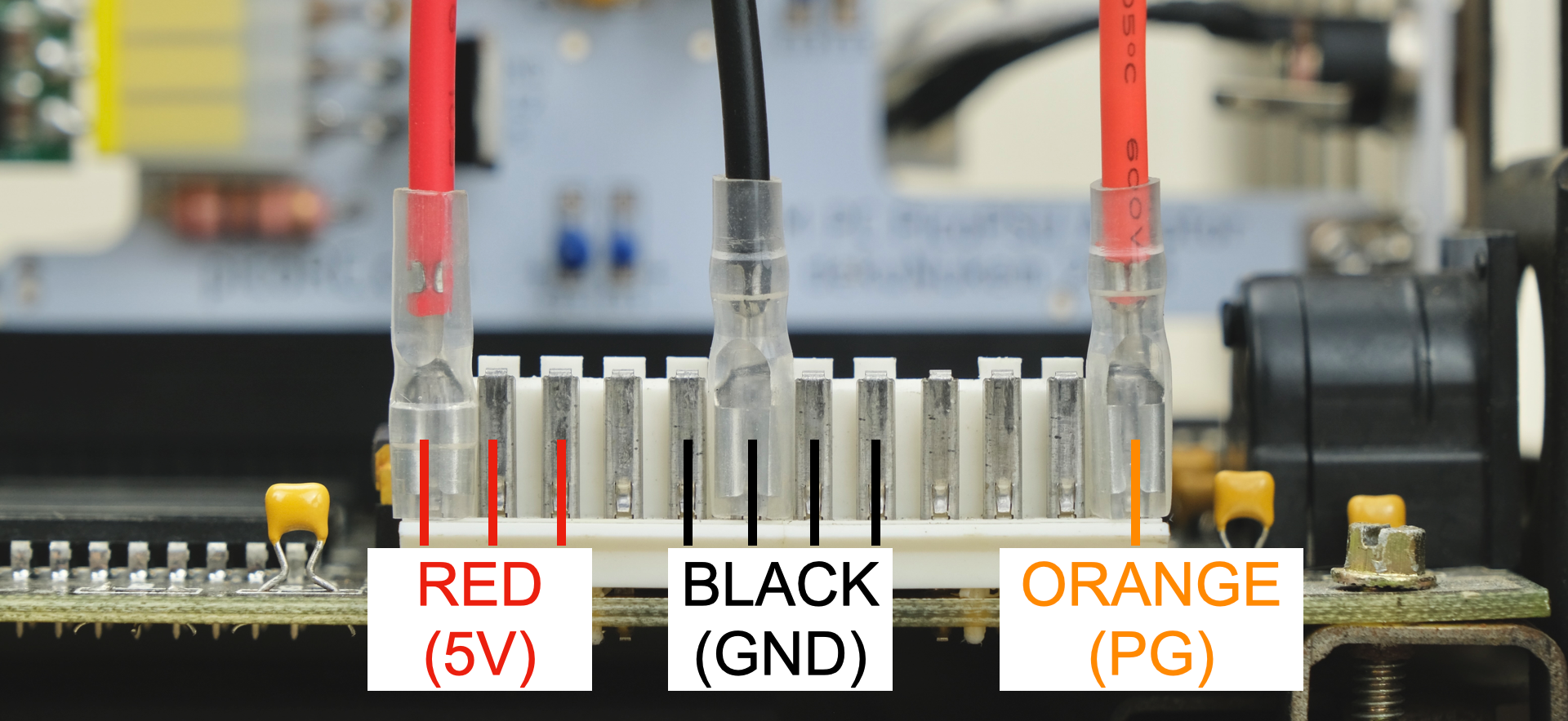
RED is +5V, can be any of the three pins on the left.
BLACK is GND, can be any of the four pins in the middle.
ORANGE is Power Good, the rightmost pin.
Make sure they are all the way in, and covered with insulation sleeve.
Double check again with the photo above.
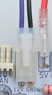
Next, plug in the CRT power cable.
Check that the purple wire faces left (12V).
Put the machine on its face, undo the two screws for the cable cage.

Feed the CRT power cable through the opening.
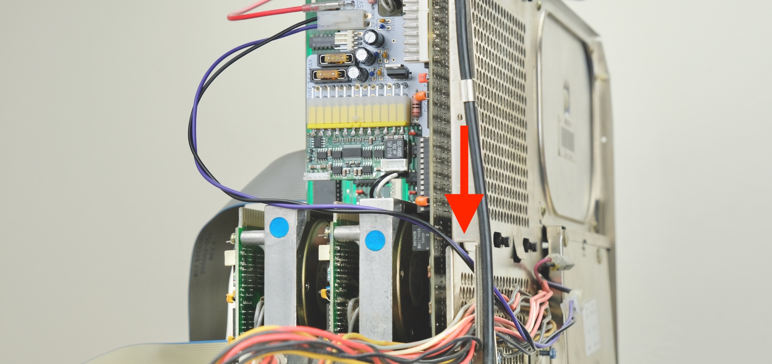
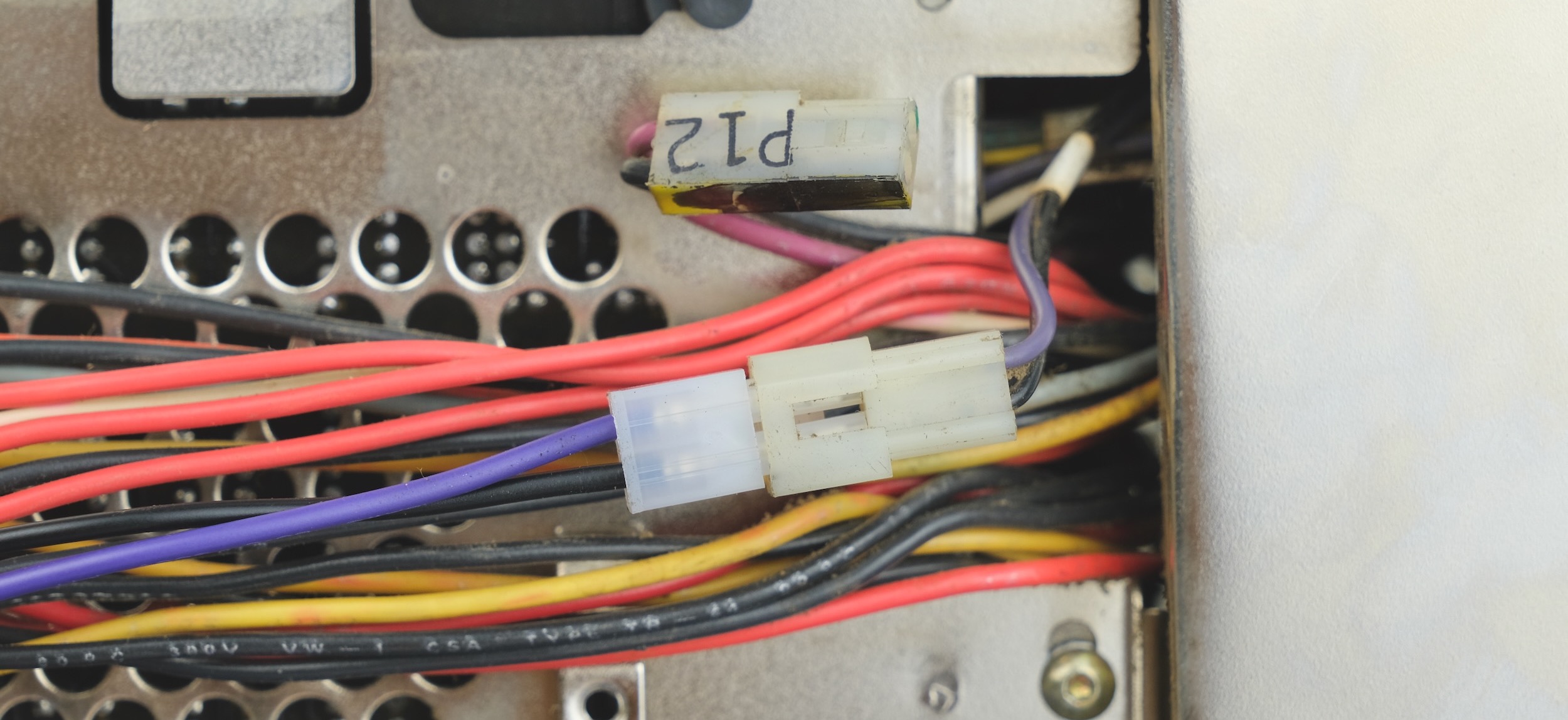
Unplug the connector labelled P12, might be tight, be gentle go slow.
Plug in the new power connector. Make sure the color match!
Reinstall the cable cage.
Moment of Truth
Now we can power on and find out if it works!
If the 5155 is of unknown condition, it is highly recommended to start minimal with just the motherboard and video card. Remove all extra cards and disconnect the drives.
Plug in and flip the switch!
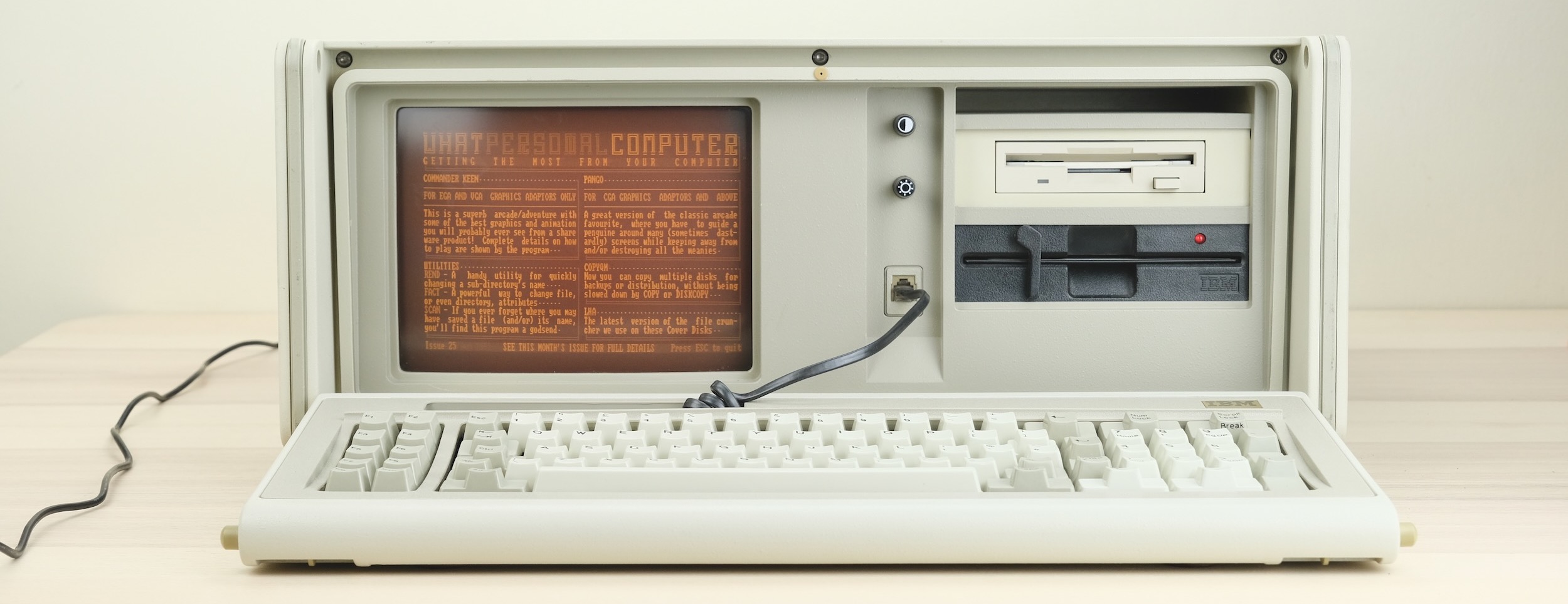
If it works, congrats! You can now add more parts back in.
If nothing happens, the tantalum capacitors on the +12V and -12V line are often the culprit, you can simply remove them. More info here.
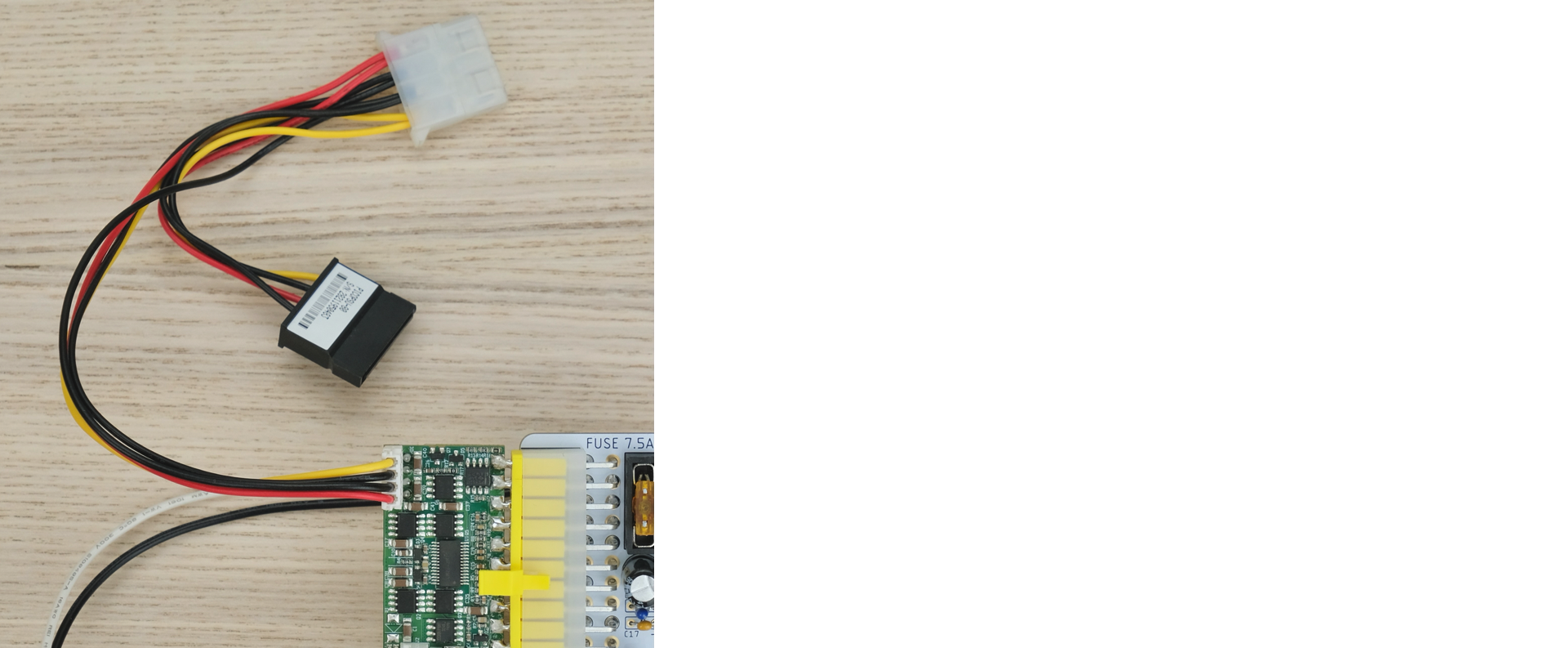
For drives, use the harness that came with the PicoPSU.
But I Want to Use the Big Red Switch™!
So far, everything we’ve done is non-destructive.
However, you can keep going and wire up the Big Red Switch™ so it can be used to power on/off the machine.
However, it requires further disassembly and cutting a few wires, so it’s up to you. Keep reading to see if it’s too much.
How It Works
There is a PSW header on the adaptor.
The PSU will turn on when the two pins are shorted together.

So we are going to take apart the old PSU, and wire up the Big Red Switch™ to those pins!
Steps
Follow the guide above, disassemble until the removal of the cable cage.

Only this time, feed all the power cables through the opening.
Also unplug the purple-and-black CRT power connector.
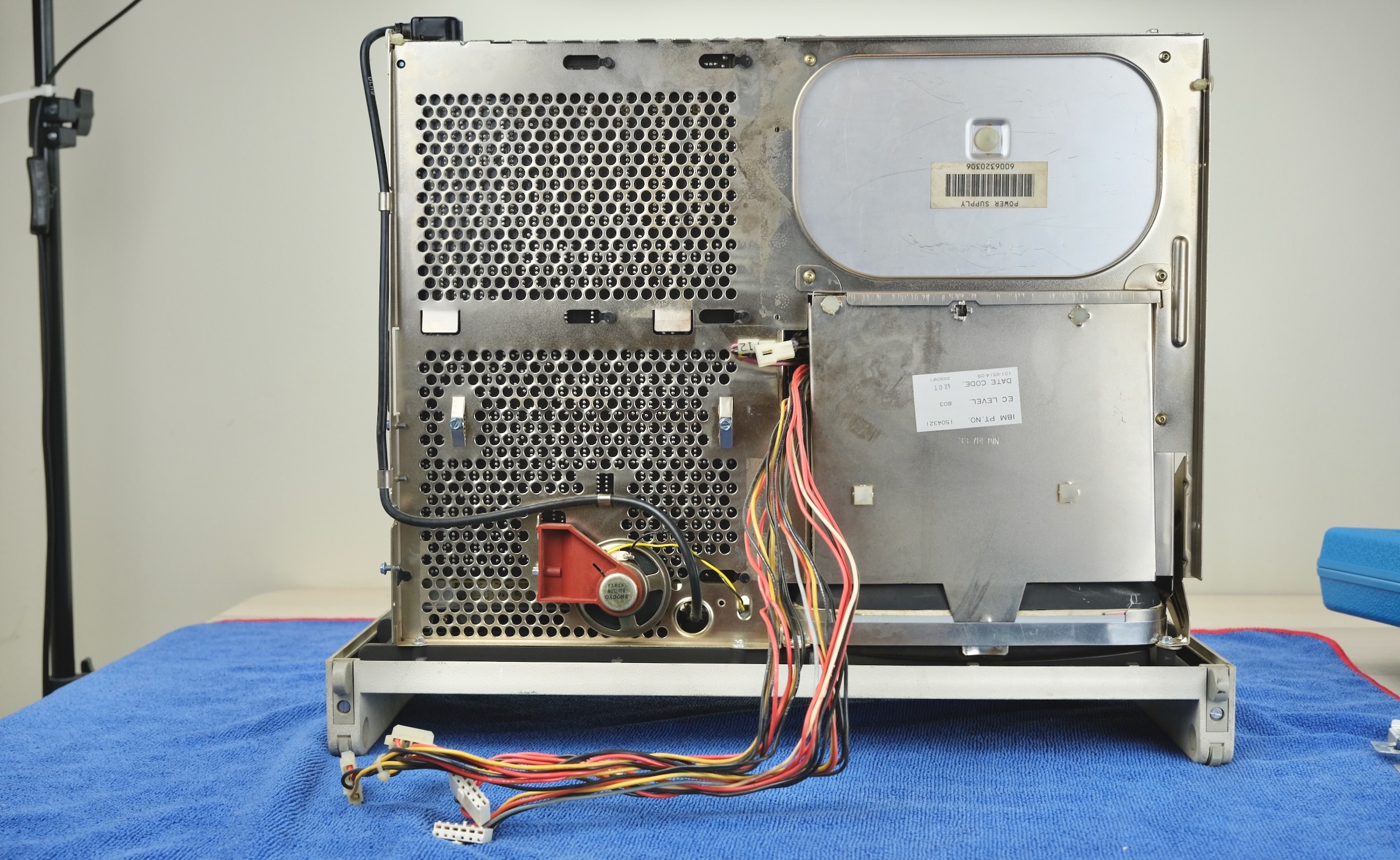
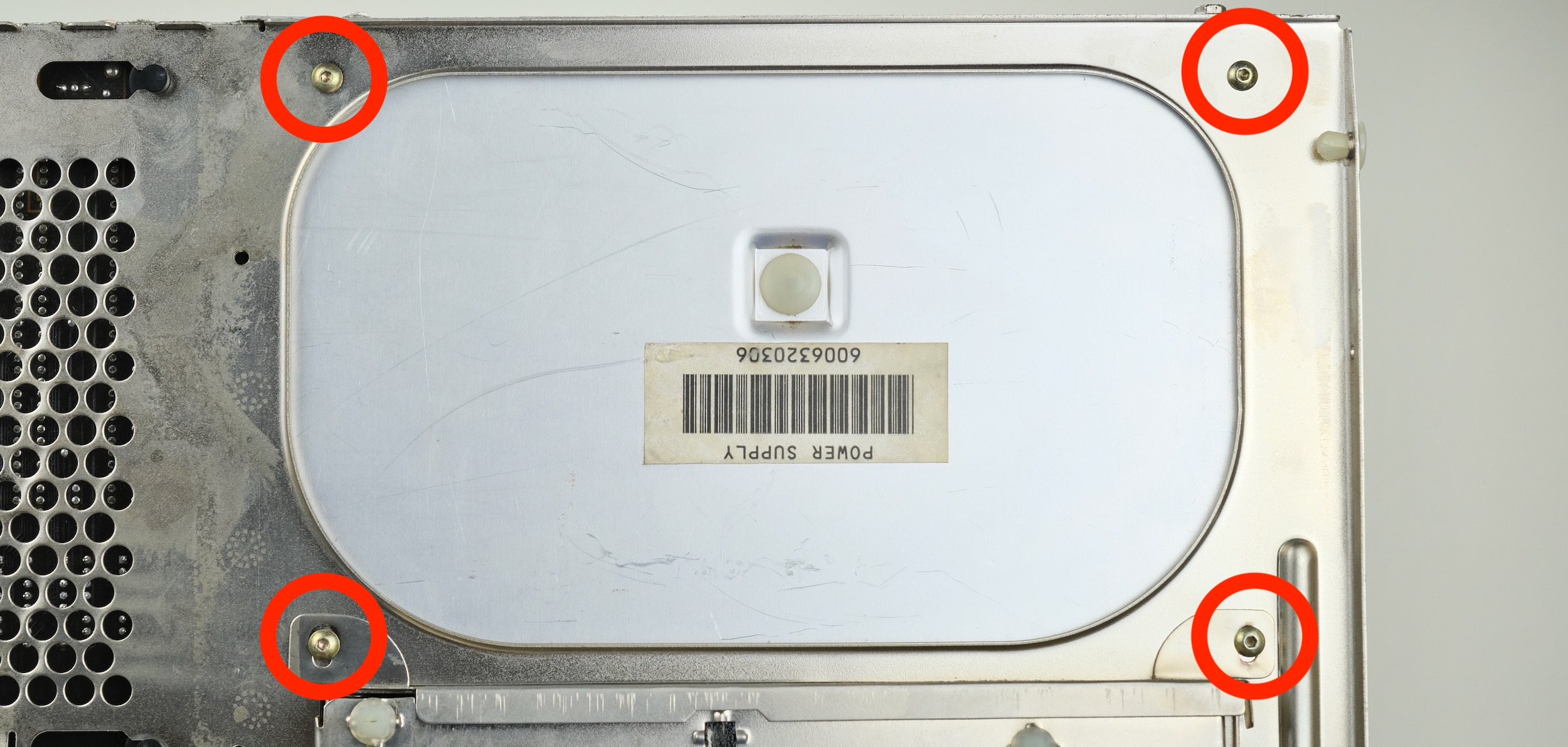
Remove the five screws securing the old PSU.
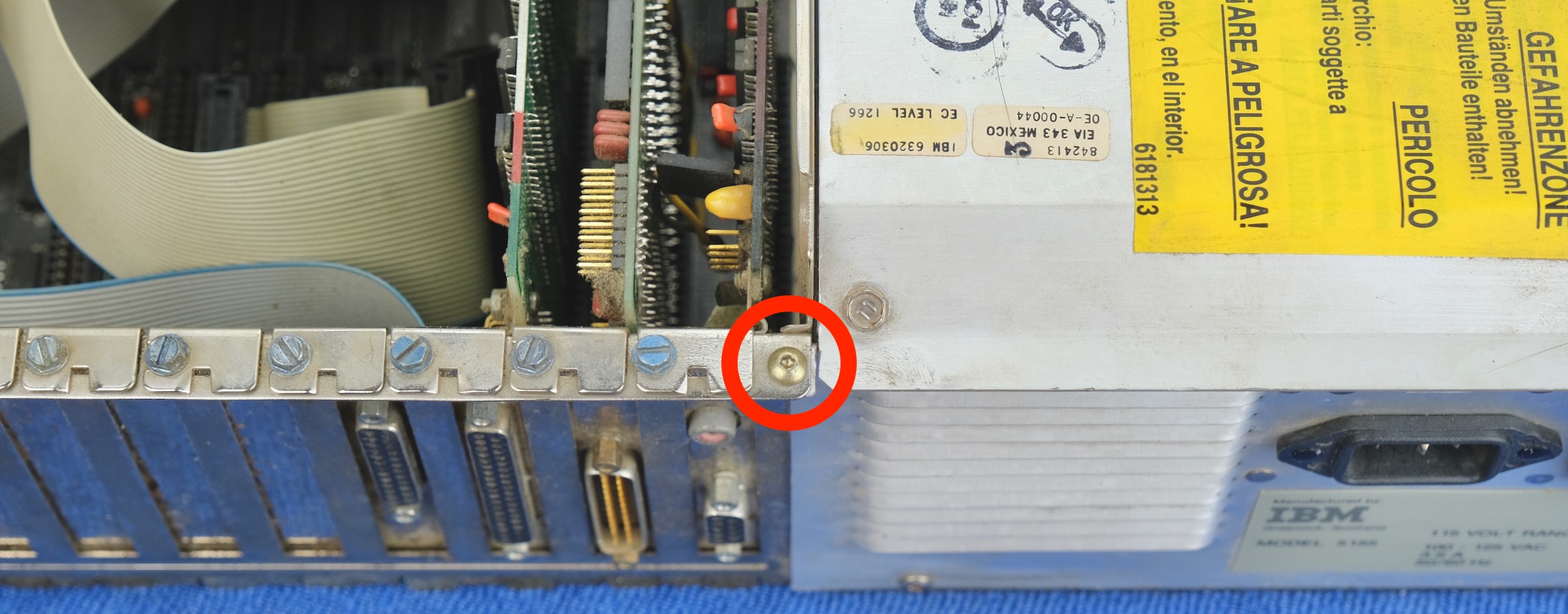
Lay the machine flat.
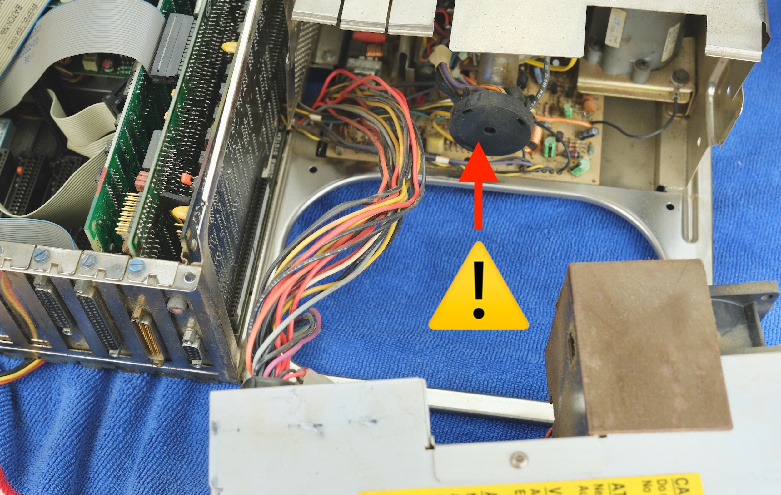
⚠️ SLOWLY ⚠️ slide the PSU outwards. It might be tight initially, DON’T RUSH!
⚠️ BEWARE OF CRT NECK of all times! ⚠️ Feed in the cable as you go.
⚠️ Don’t bump the neck! ⚠️ It’s game over if it’s broken.
Eventually, you’ll completely remove the PSU.
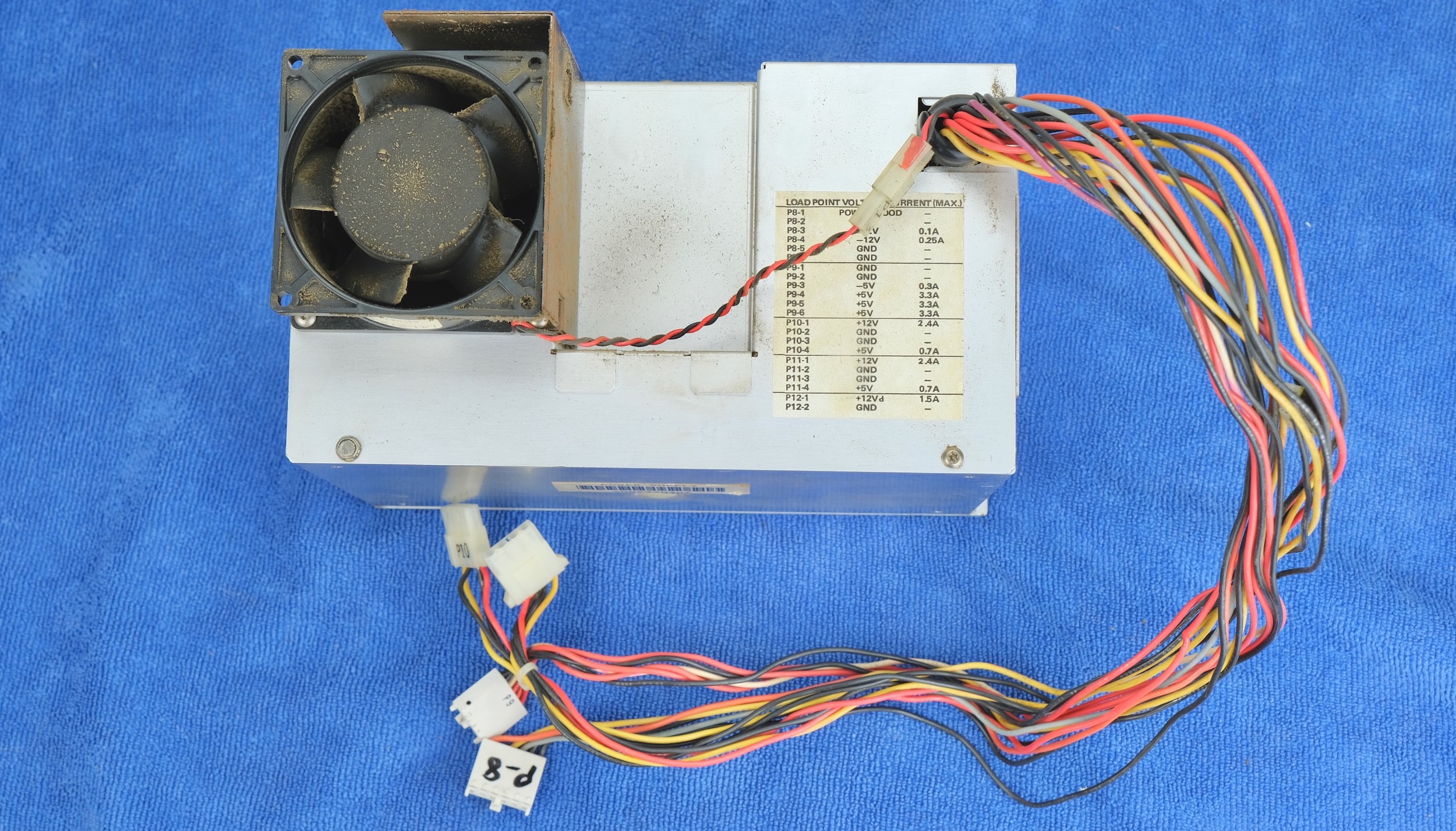
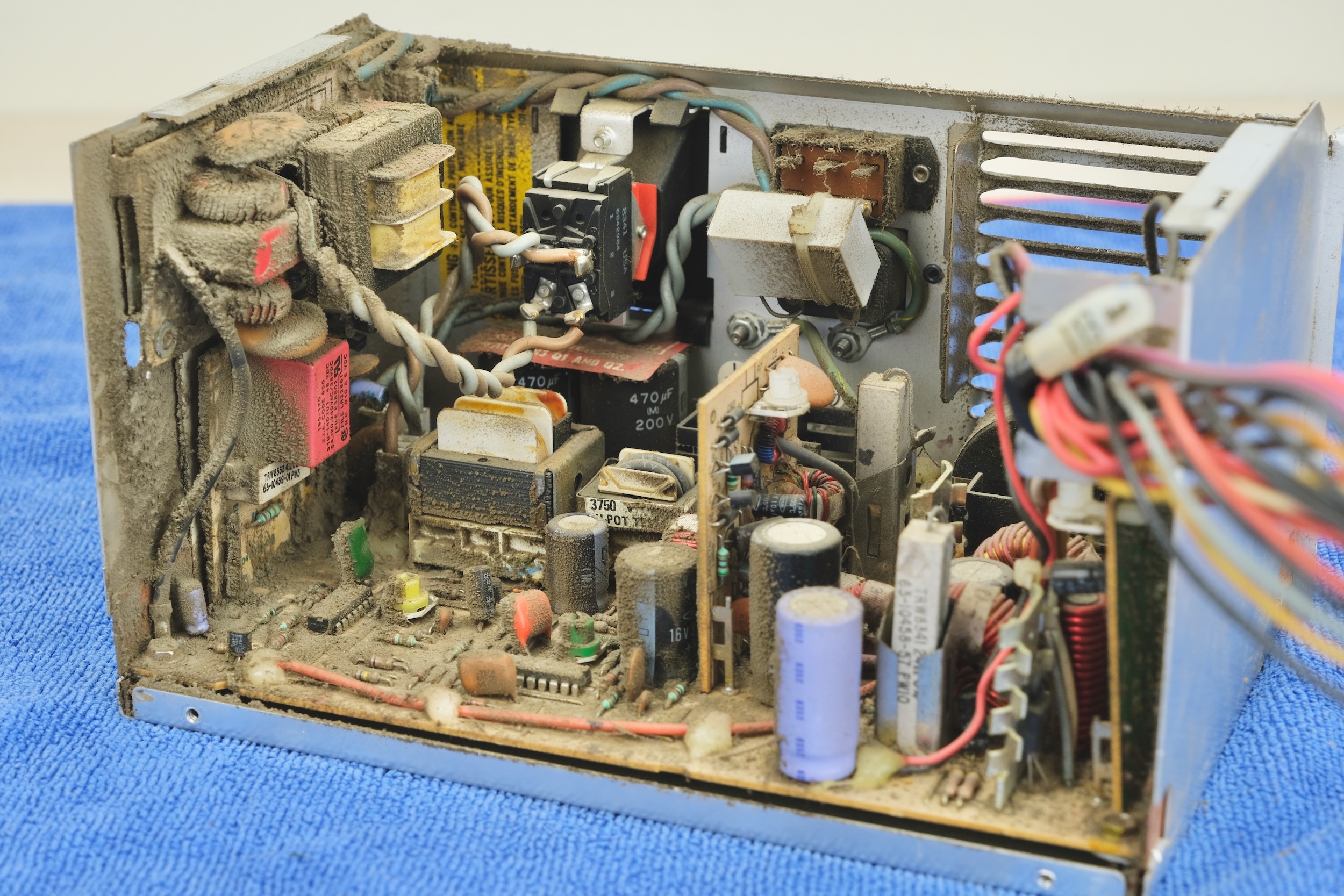
Remove the four screws shown to open it up.


Yikes!
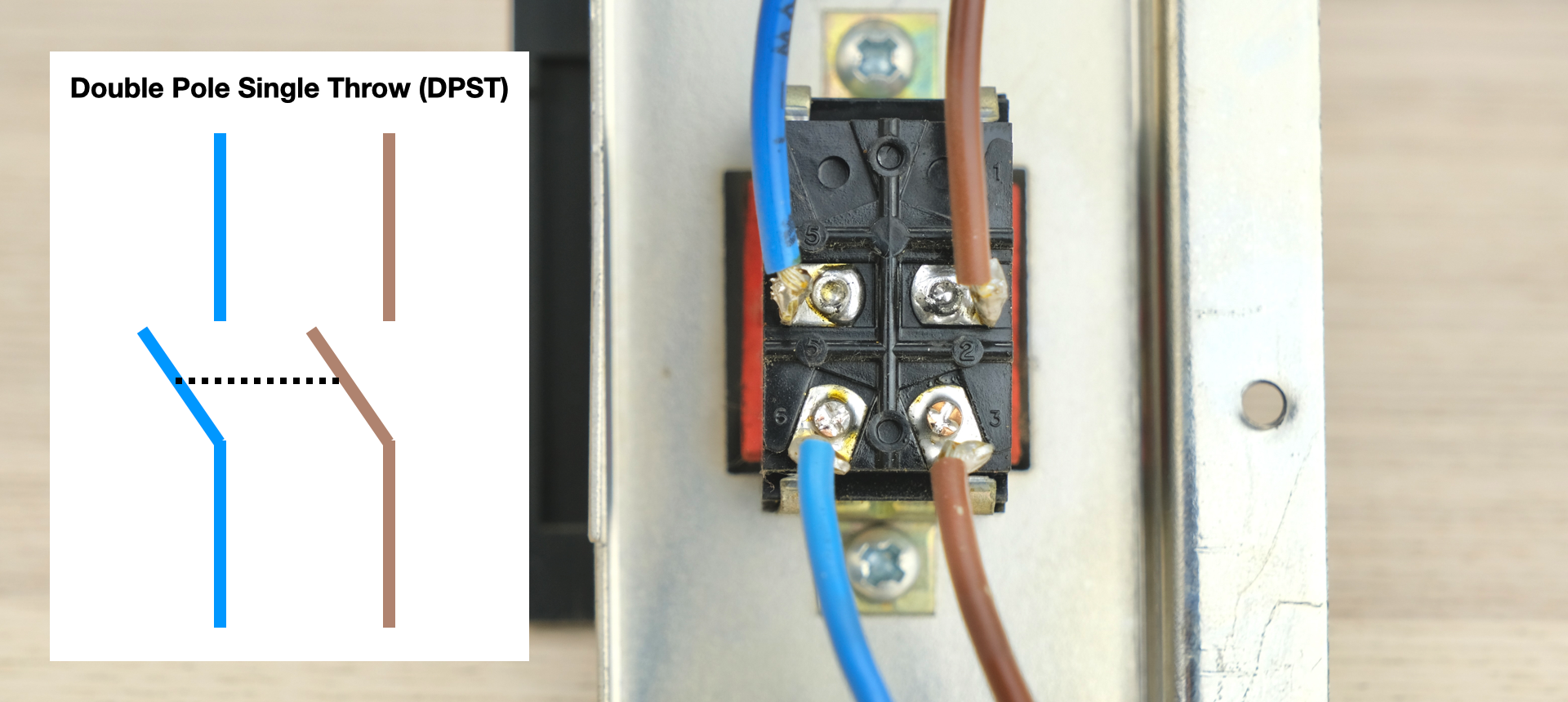
The Big Red Switch™ is a Double Pole Single Throw (DPST) switch, which switches two circuits at once.
Note the colour of the wires.
The same colored wire are connected together when the switch is on.
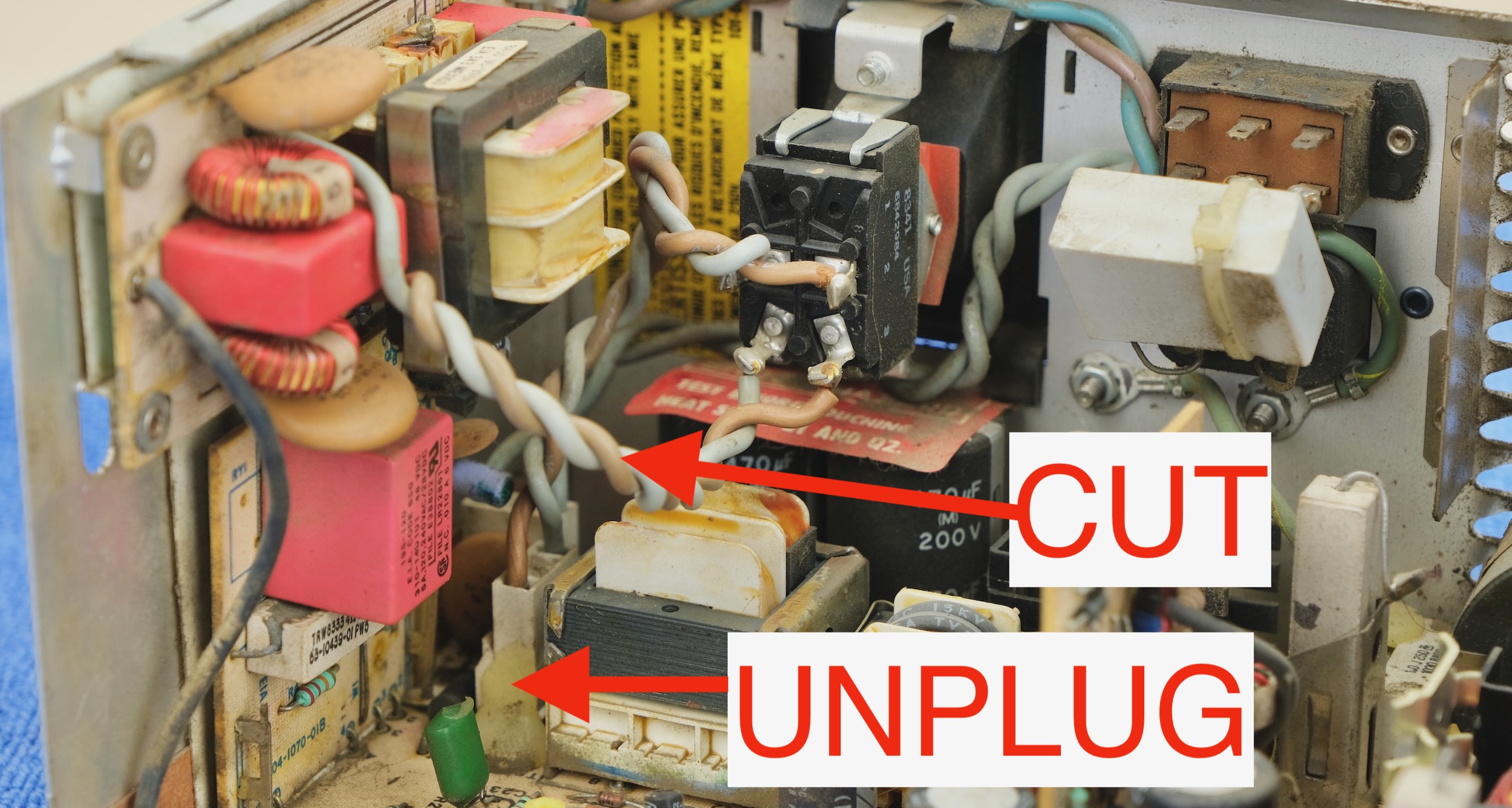
⚠️⚠️ MAINS VOLTAGE flows through this switch!!! ⚠️⚠️ For safety, we’ll need to disconnect those wires.
UNPLUG the connector, and CUT the other two wires.
Now the Big Red Switch™ should be completely isolated.
Double check that this is the case.
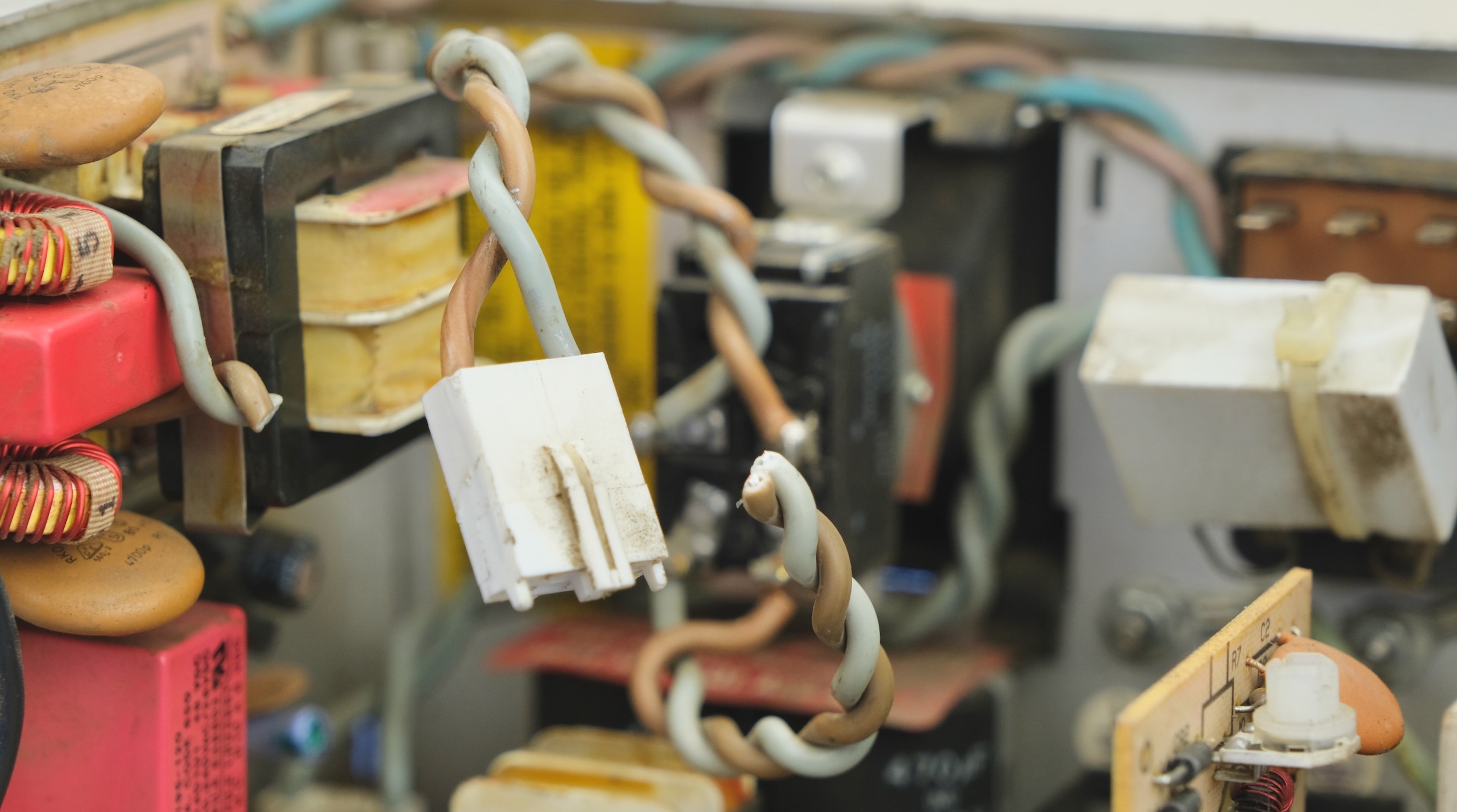
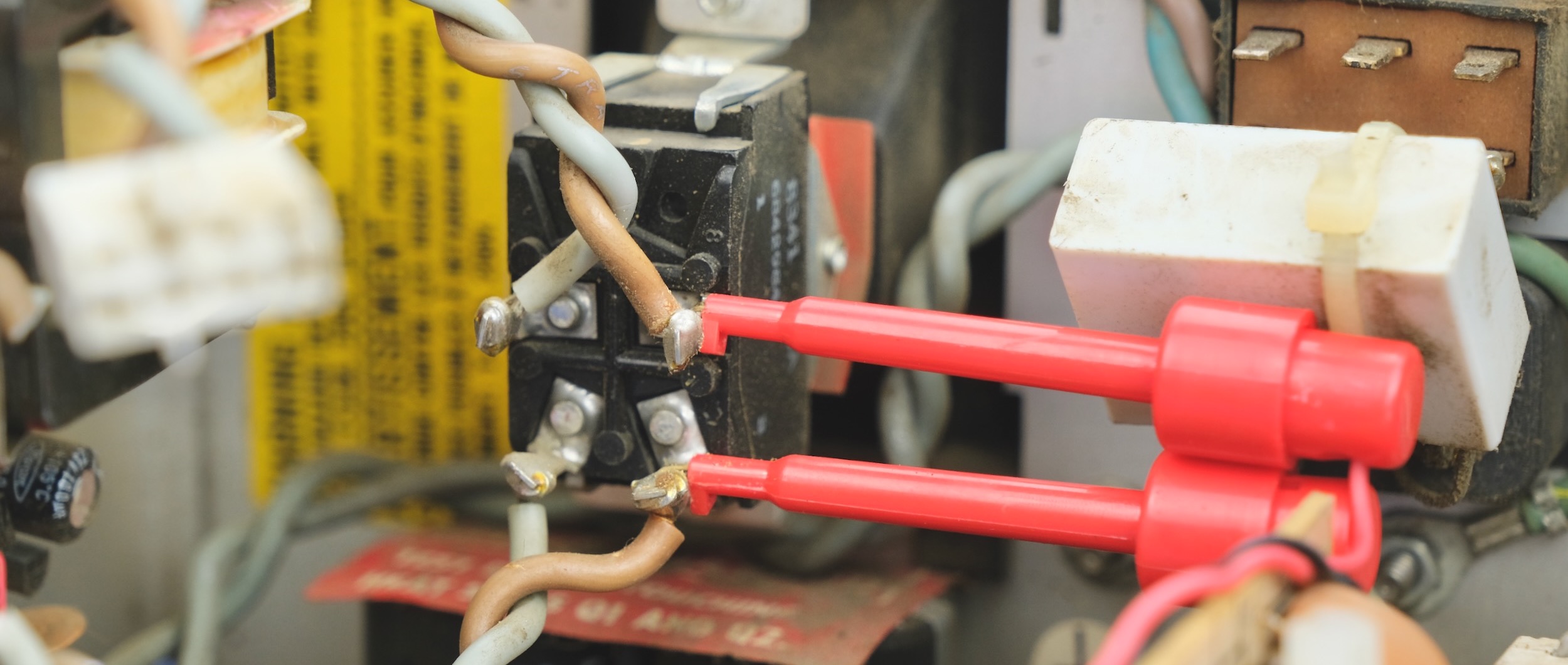
Attach the test clips to one side of the switch.
To assemble the test clip, pull off the cap, insert the wire through the hole in the cap, solder the wire, and reinstall the cap.
You can also solder the wires directly to the terminals.

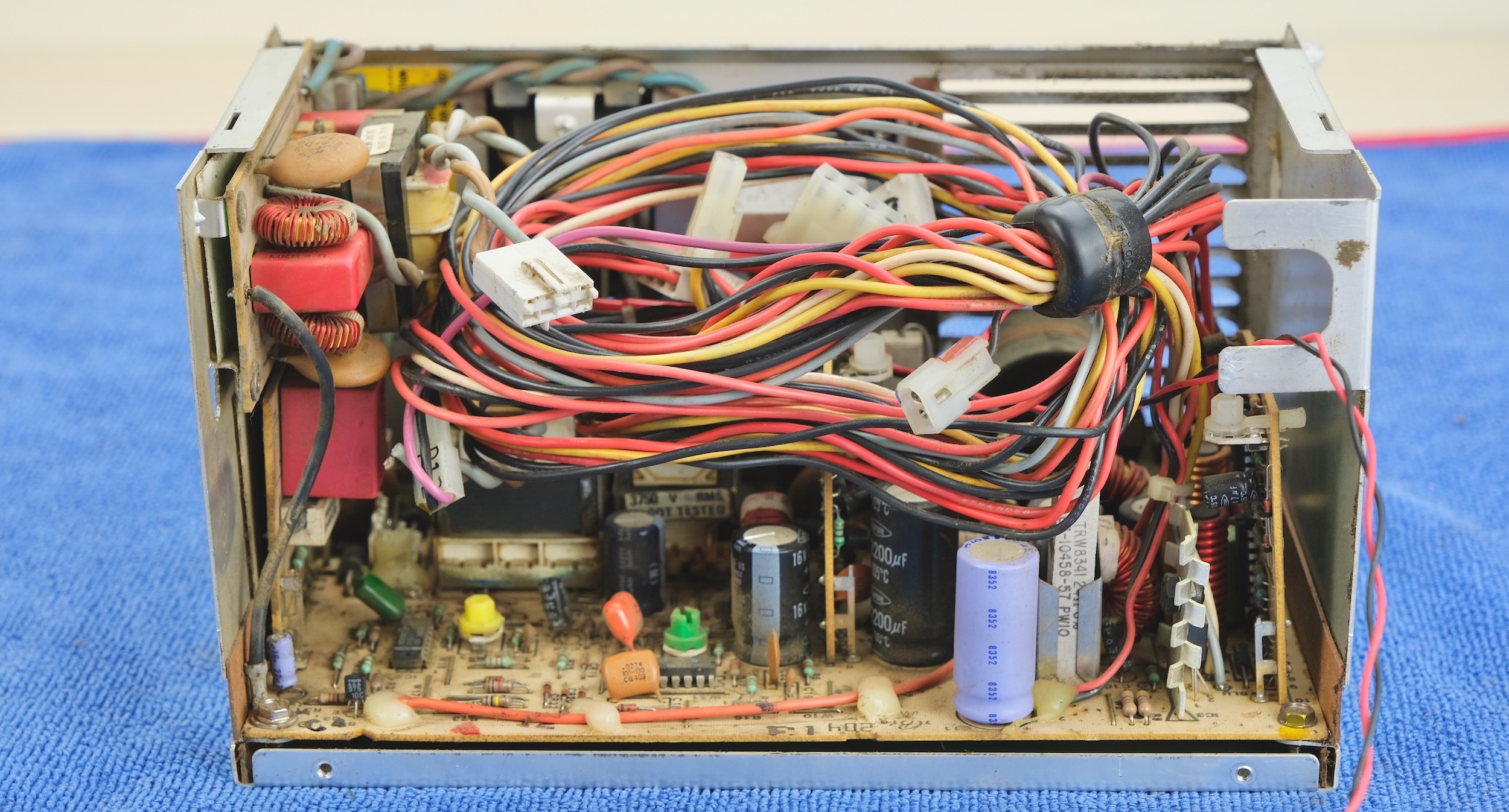
Tuck all the original wiring inside the case. We won’t be using them anymore.
Make sure they don’t knock loose the test clips.
Now the Big Red Switch™ wires should be the only thing that exits the case.
It’s also a good opportunity to replace the original cooling fan.
Any good quality 80mm PC fan should work.
Don’t discard the black metal bracket! It shields the CRT from the electromagnetic field of the fan motor. Without it, the picture will wobble.
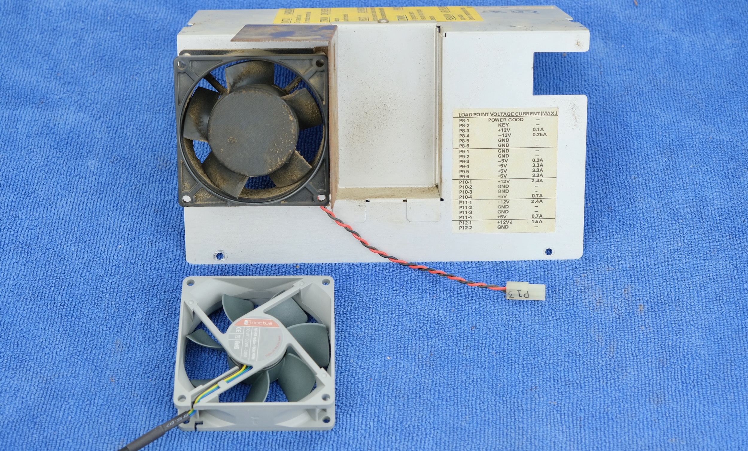
With the new fan, TAPE OVER THE HOLE of the old wire harness to improve cooling efficiency.
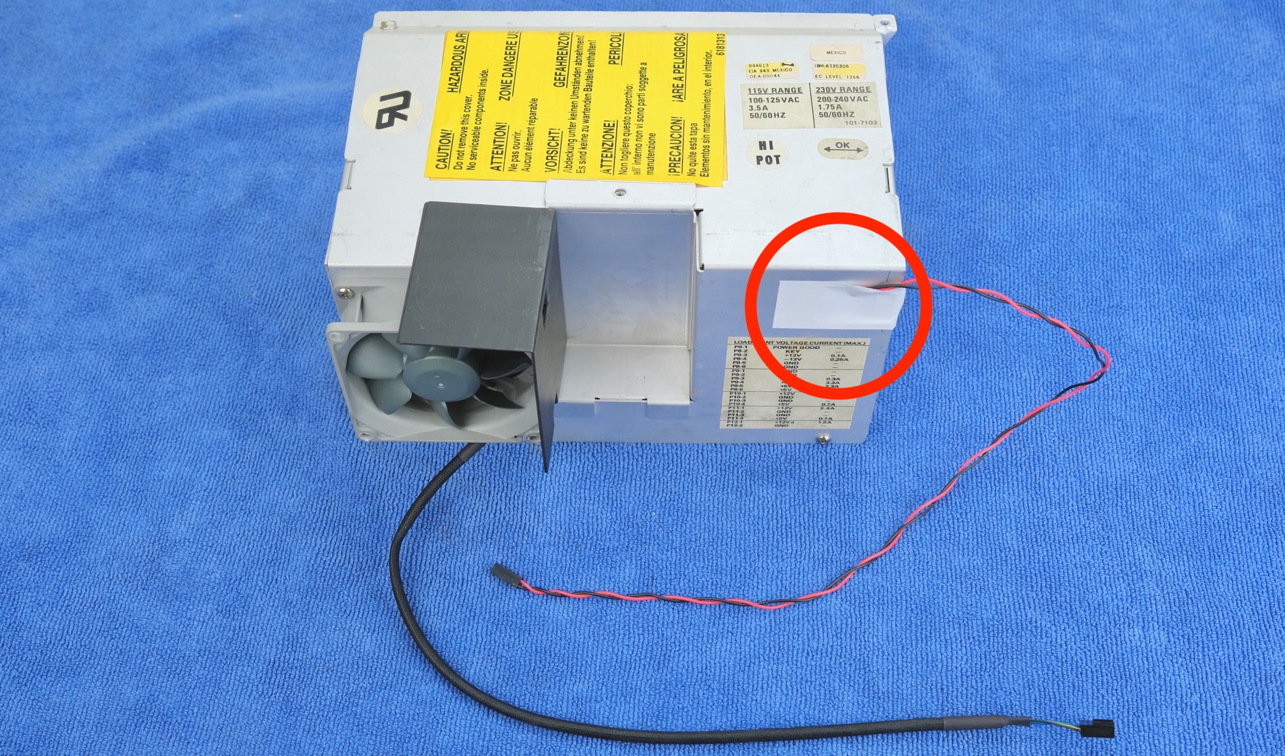
Now reinstall the PSU.
⚠️ CAREFUL WITH THE CRT NECK ⚠️
Don’t forget to thread the CRT connector through the opening in the bottom.
Connect it back up. Make sure the colors match.
Reinstall the cable cage.
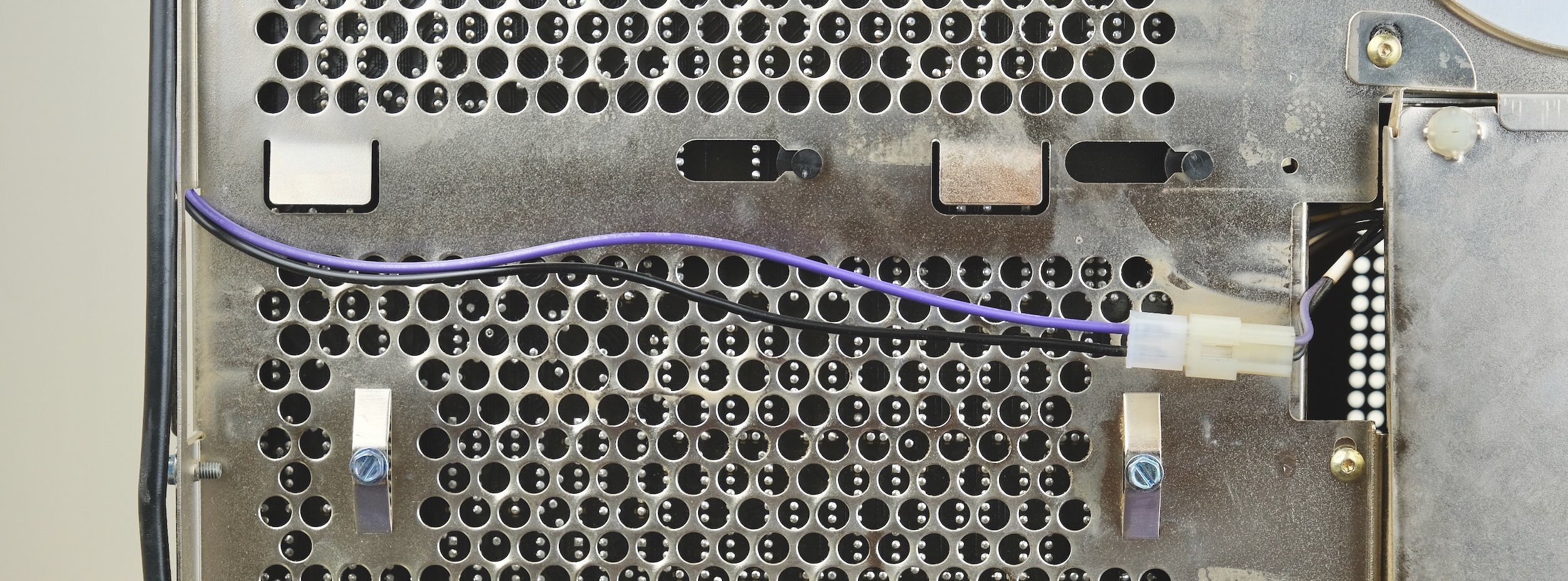
Plug the fan header and power switch header into the adaptor.
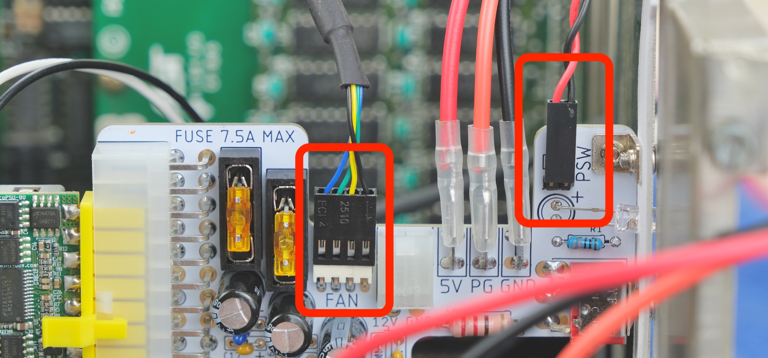
That’s pretty much it! Test to make sure it works, and reassemble!
Questions or Comments?
Feel free to ask in official Discord Chatroom, raise a Github issue, or email dekunukem gmail.com!