PicoRC
PicoRC PSU Kit for Osborne 1
| Purchase Link | Official Discord |
A Drop-in Replacement Power Supply Unit for Osborne 1
- Non-destructive and Reversible
- Reuses Existing Hardware
- Original Appearance
- Modern PC Fan Support
- Quieter & improved cooling
- Mean Well PSU with Fused Rails
- Low-cost and reliable
Supports BOTH early (side latch) and late (top latch) models.
Get One / Other Stuff
Also available for many other computers.
For more general-purpose diagnostics and retrofitting, check out the full-fat ATX4VC.
Additional Shopping
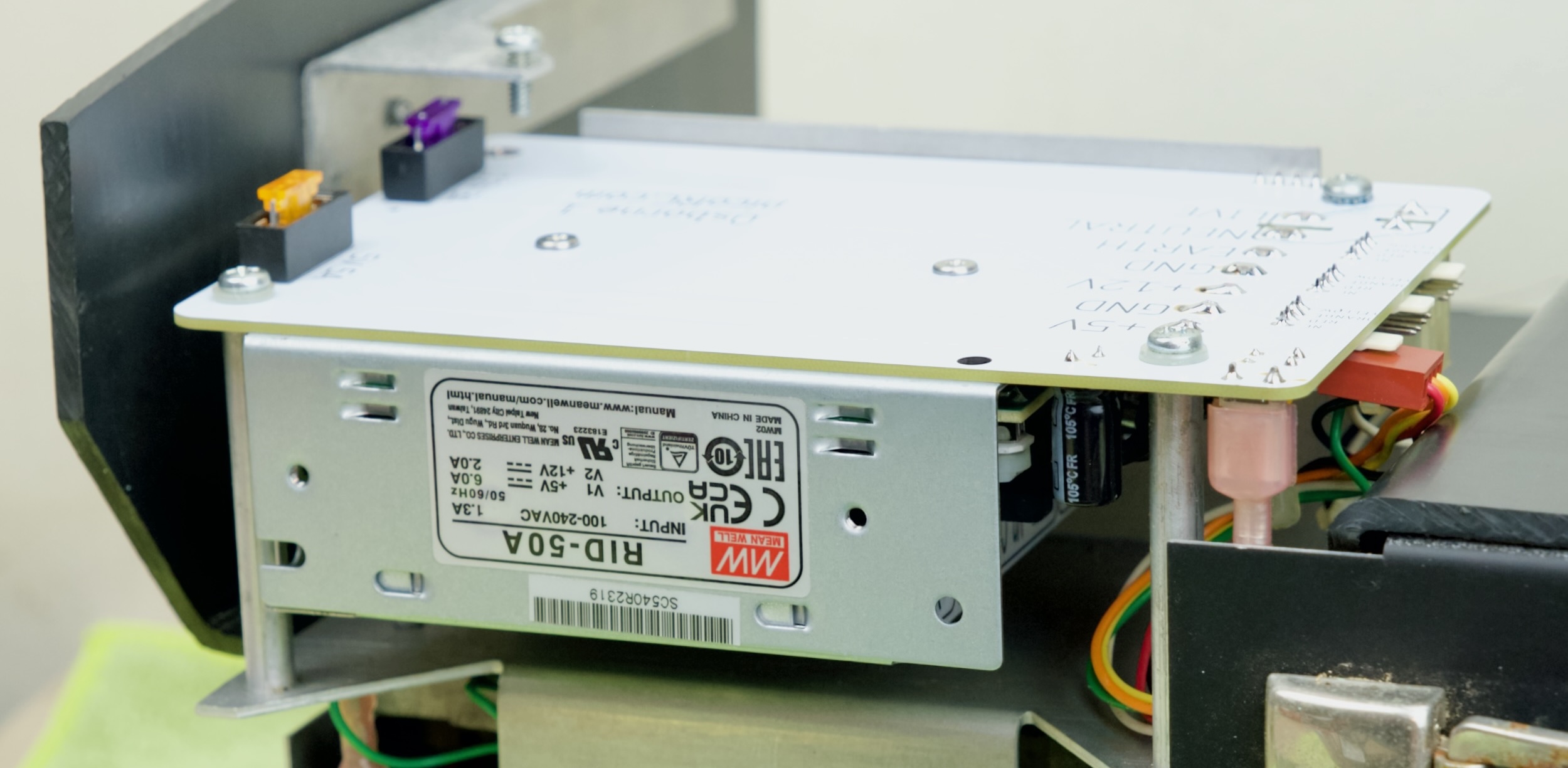
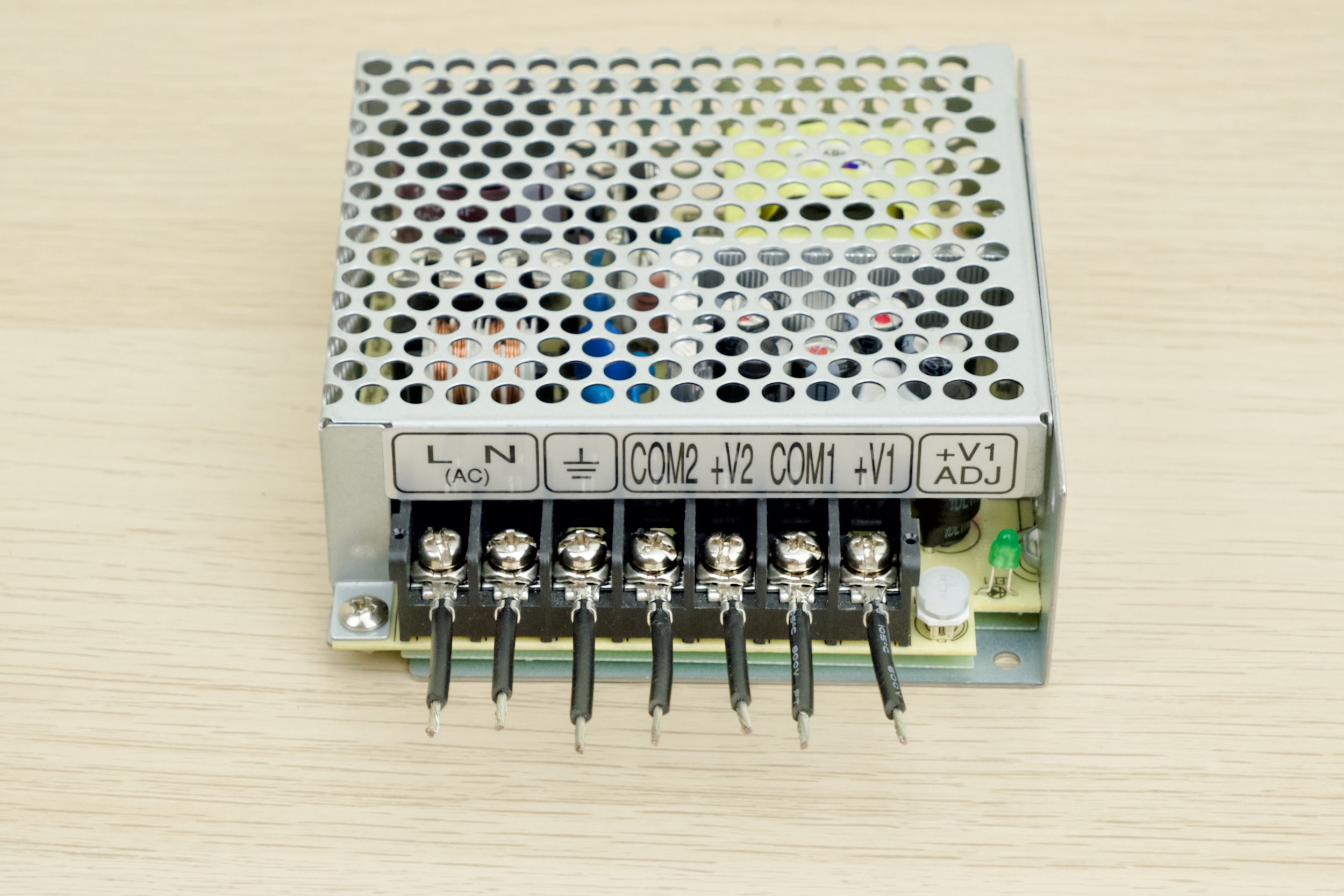
Apart from the kit itself, you need to buy a Mean Well PSU.
- Both Mean Well RD-50A and RID-50A works
⚠️ ⚠️ MAKE SURE IT IS THE “A” VARIANT! ⚠️ ⚠️
- Around 20 USD / GBP
- Buy from a reputable distributor, NOT eBay or Aliexpress!
- Mouser
- DigiKey
- RS Components, etc.
Kit Assembly
DON’T START YET!!! Keep reading :)
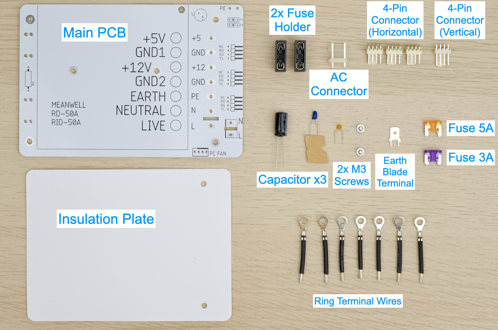
Observe the parts:
Soldering Notes
Nothing too tricky in this kit, all basic through-hole parts.
If this is your first time:
- Ensure your soldering iron has proper temperature control
- Try your local makerspace or university lab
- Use leaded solder and plenty of flux
- Temperature around 350C / 660F.
- This video covers the basics pretty well
- Start from shortest to tallest.
- Solder a single pin first, ensure it is straight, adjust if necessary.
Assembly
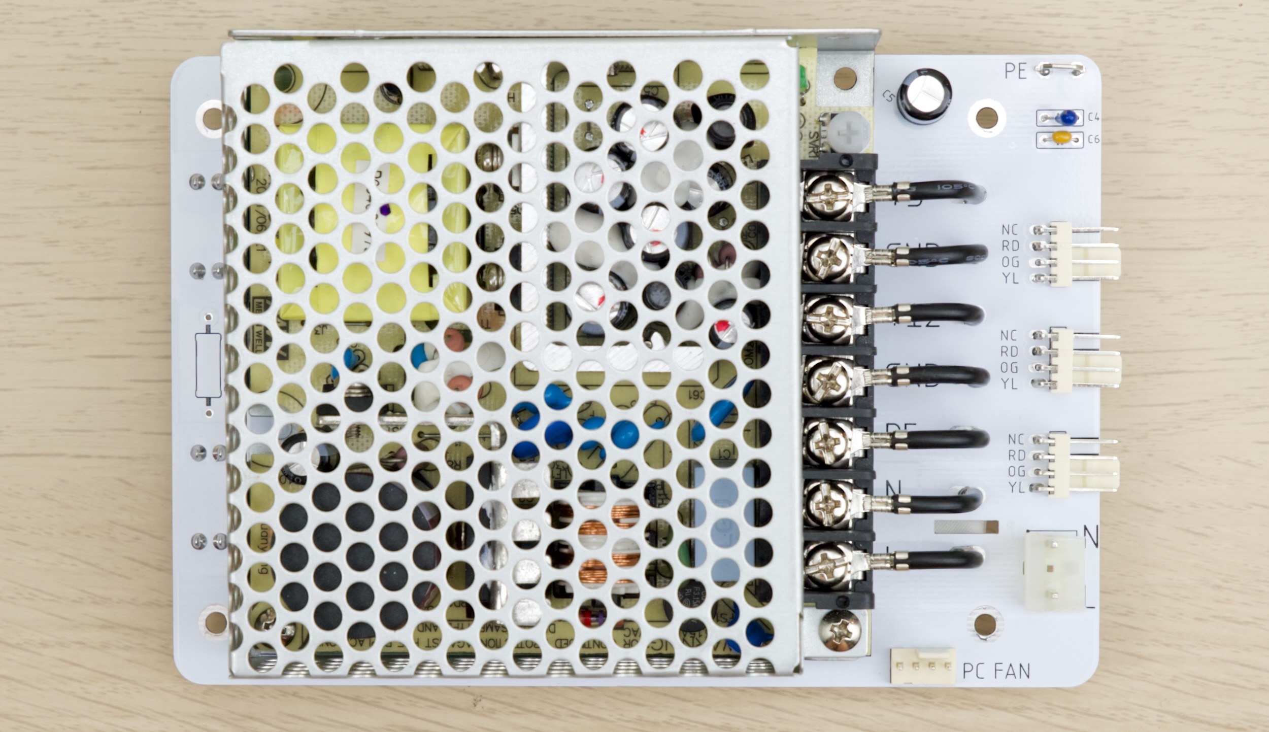
Solder the following components on top side:
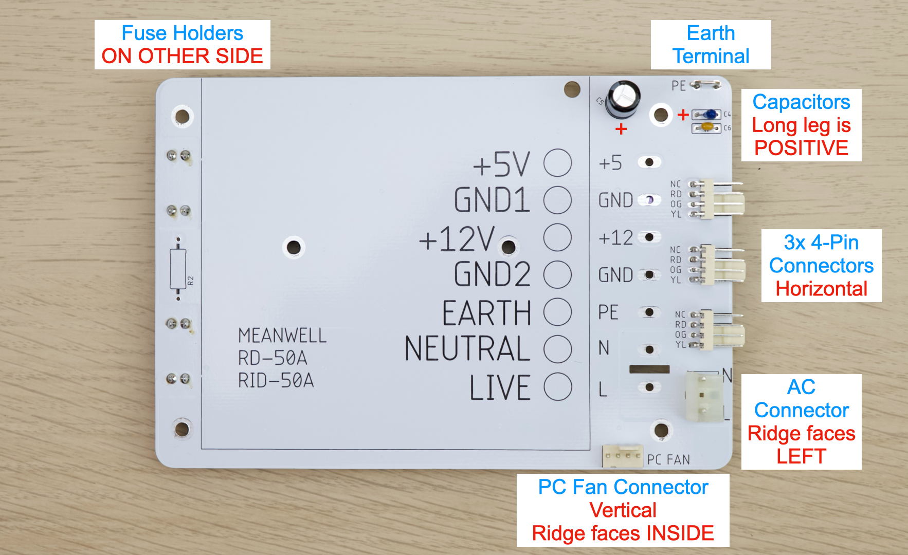
- Double check polarity!
- Black electrolytic capacitor: White stripe is NEGATIVE.
- Blue Tantalum capacitor: White stripe is POSITIVE.
- Yellow ceramic capacitor: No polarity.
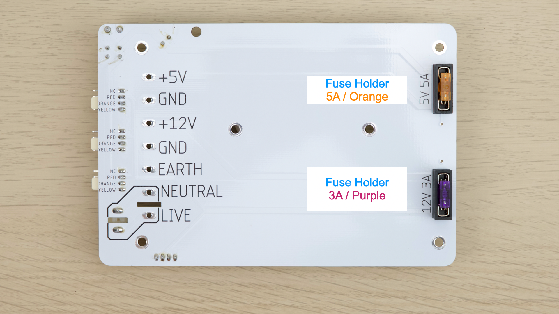
Flip over, on bottom side:
- Solder the fuse holders
- Install fuses
On Mean Well PSU:
- Undo screws
- Insert ring terminal
- Redo screws
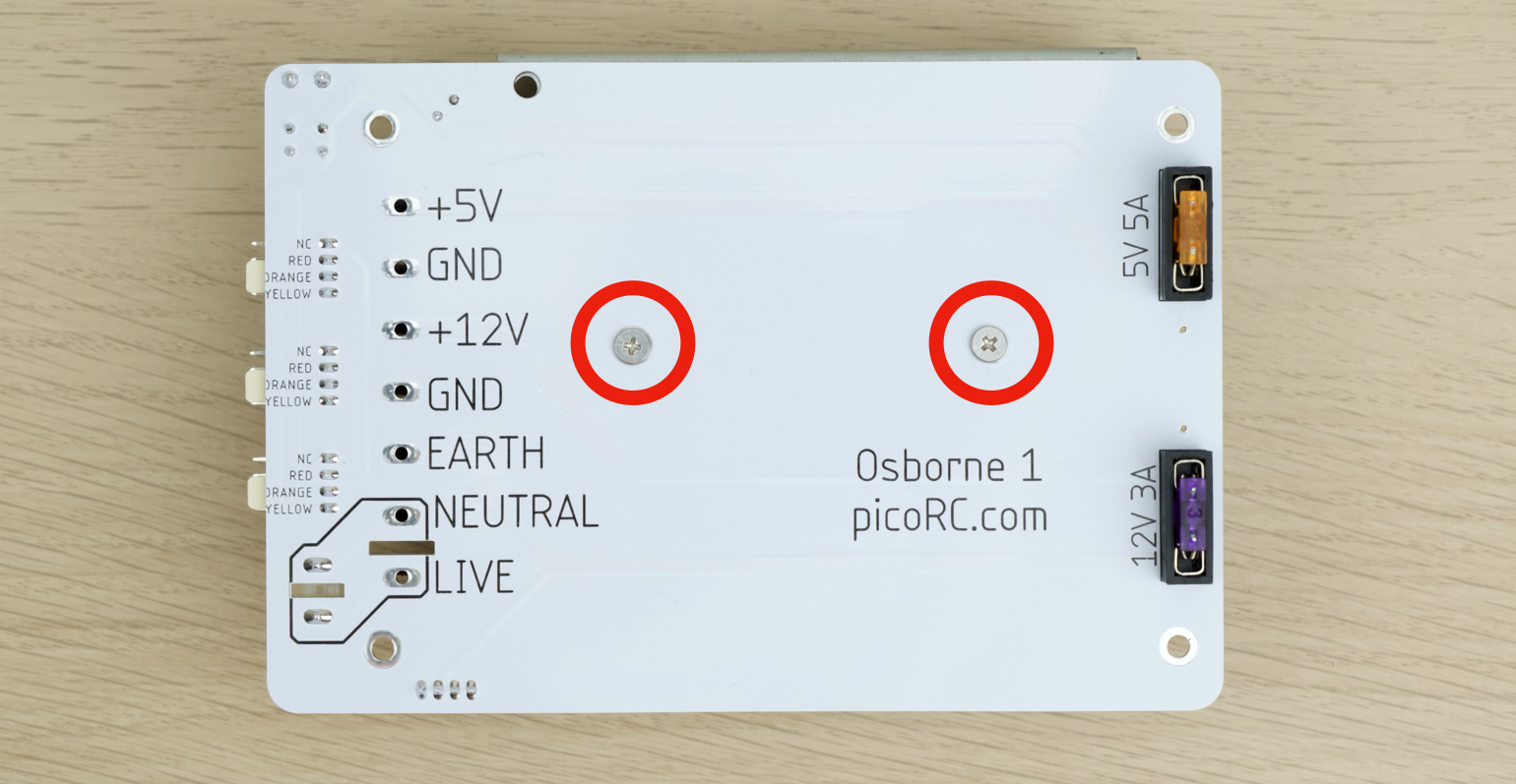
Attach the Mean Well PSU to the PCB with two M3 screws
- Flip over
- Twist the strands
- Insert though corresponding holes
- Ensure NO LOOSE STRANDS on the top side
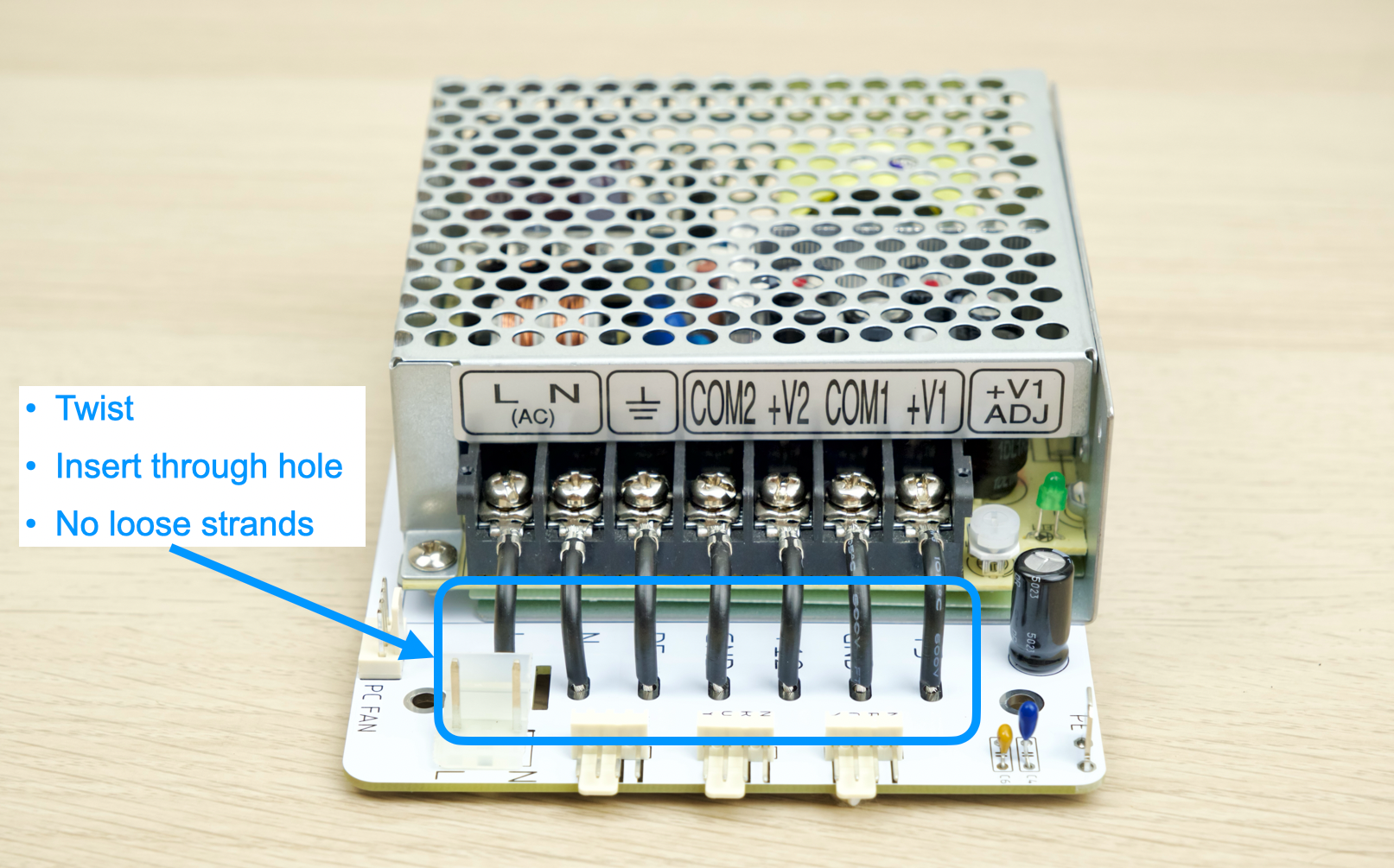
- Solder down the wires
- Trim excess length
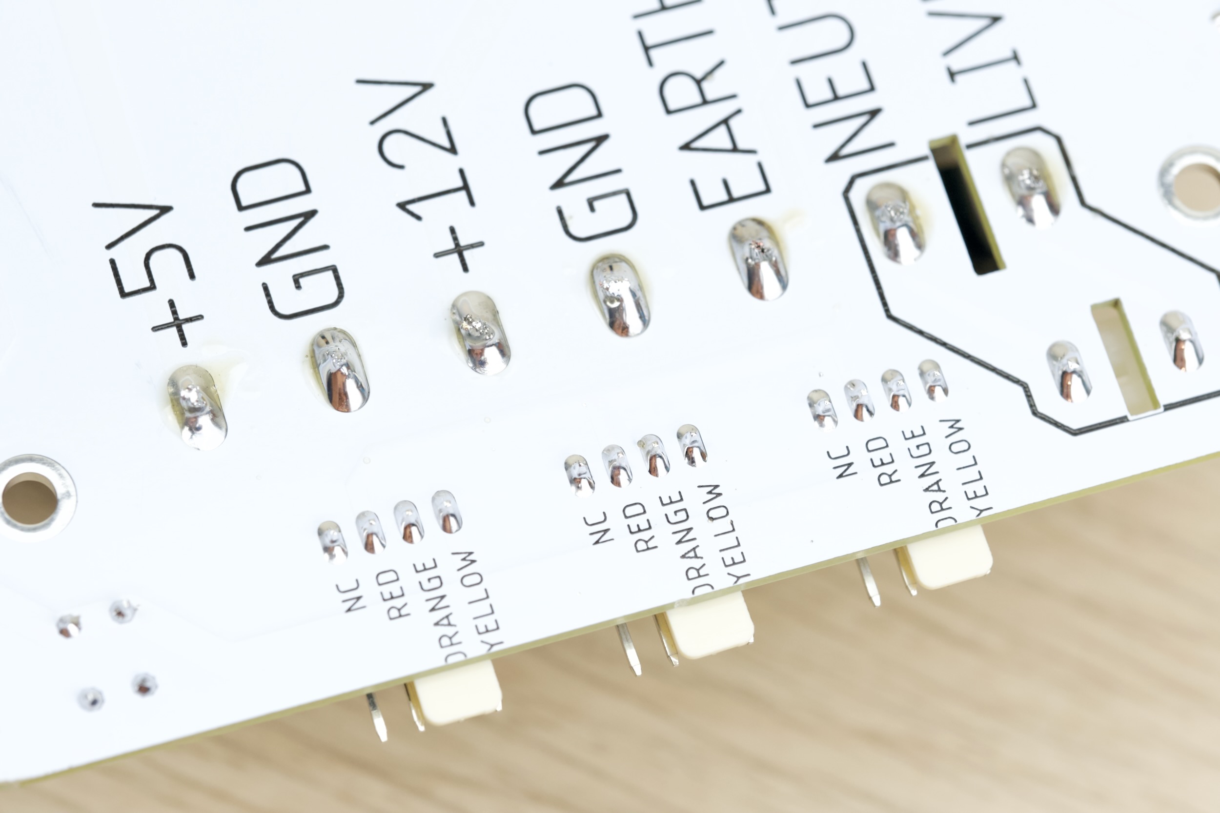
Inspection
- Compare with photos above
- Solder joints should be shiny and smooth
- There must be no solder bridges
- If any, add flux and melt to remove.
Installation
-
🚨🚨 This guide is for LATE MODEL (TOP LATCH), CLICK ME FOR EARLY MODEL (SIDE LATCH) 🚨🚨
-
🚨🚨 This guide is for LATE MODEL (TOP LATCH), CLICK ME FOR EARLY MODEL (SIDE LATCH) 🚨🚨
Some disassembly is needed, make sure to take plenty of photos along the way!
Take a photo before removing a screw or unplugging a connector! It never hurts to have reference.
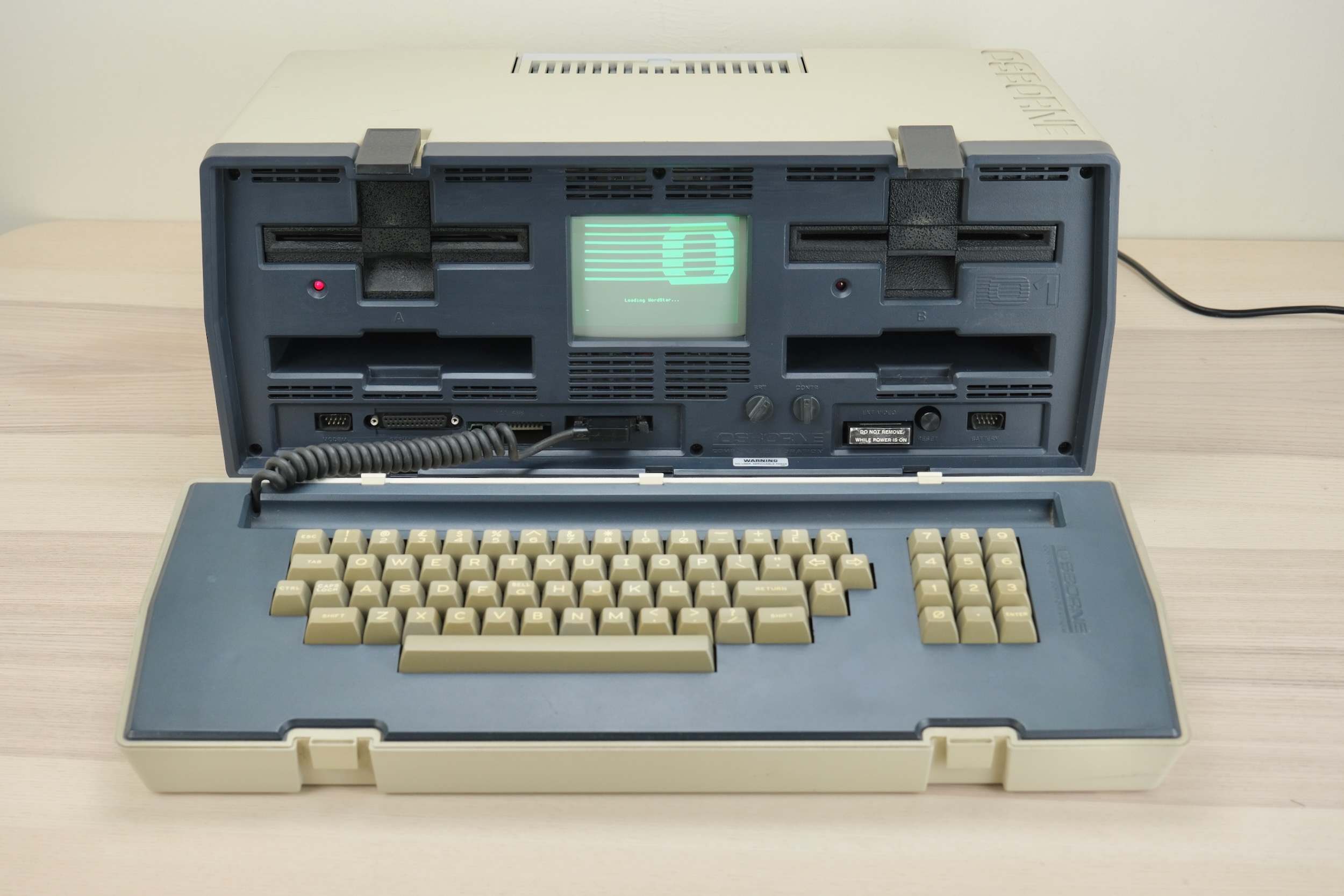
I’m using a new-to-me and untested Osborne 1 in this guide, excuse the dust!
- Place on a soft towel, unlatch and unplug the keyboard.
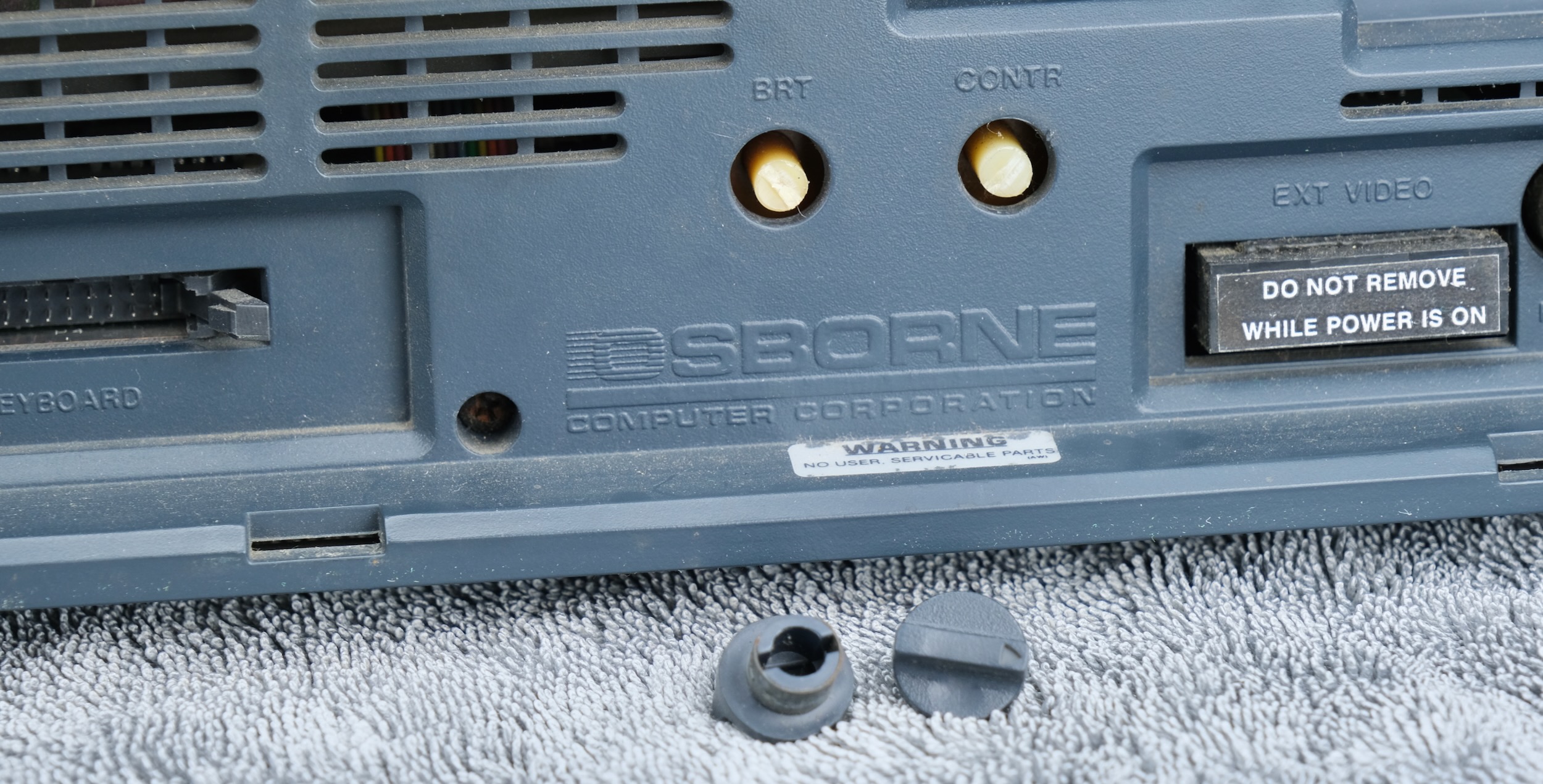
- Remove brightness and contrast knob
- If has grub screw, loosen first.
- Otherwise just pull it off
- Undo the 6 face plate screws
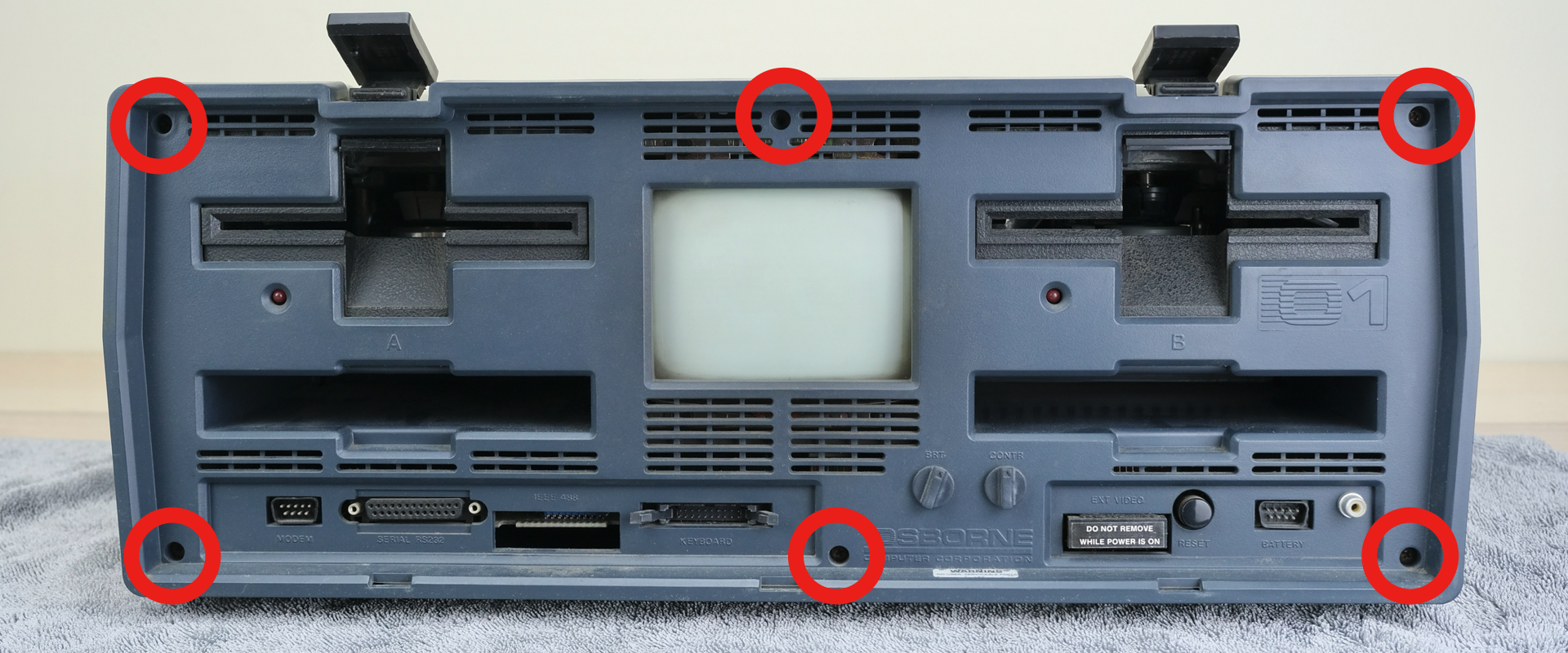
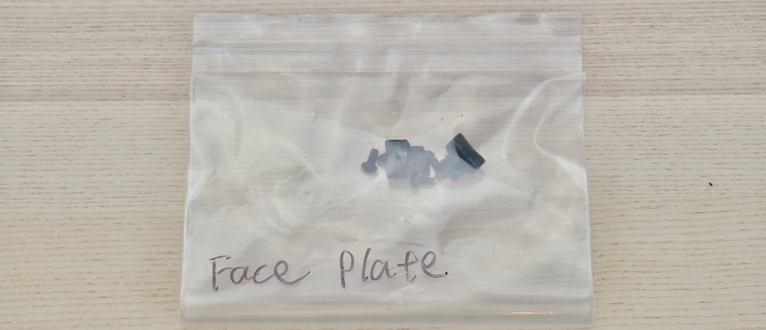
- Organise your screws!
- At each stage, put them in a bag with labels to avoid mix-ups.
- Flip over
- Undo five screws
- Remove the bottom cover
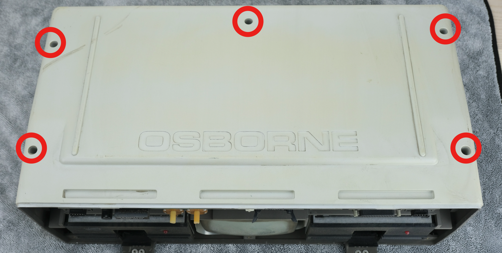
- Turn it around
- Lift off the handle plate
- Remove four screws shown
- Don’t forget the earthing lug during reassembly
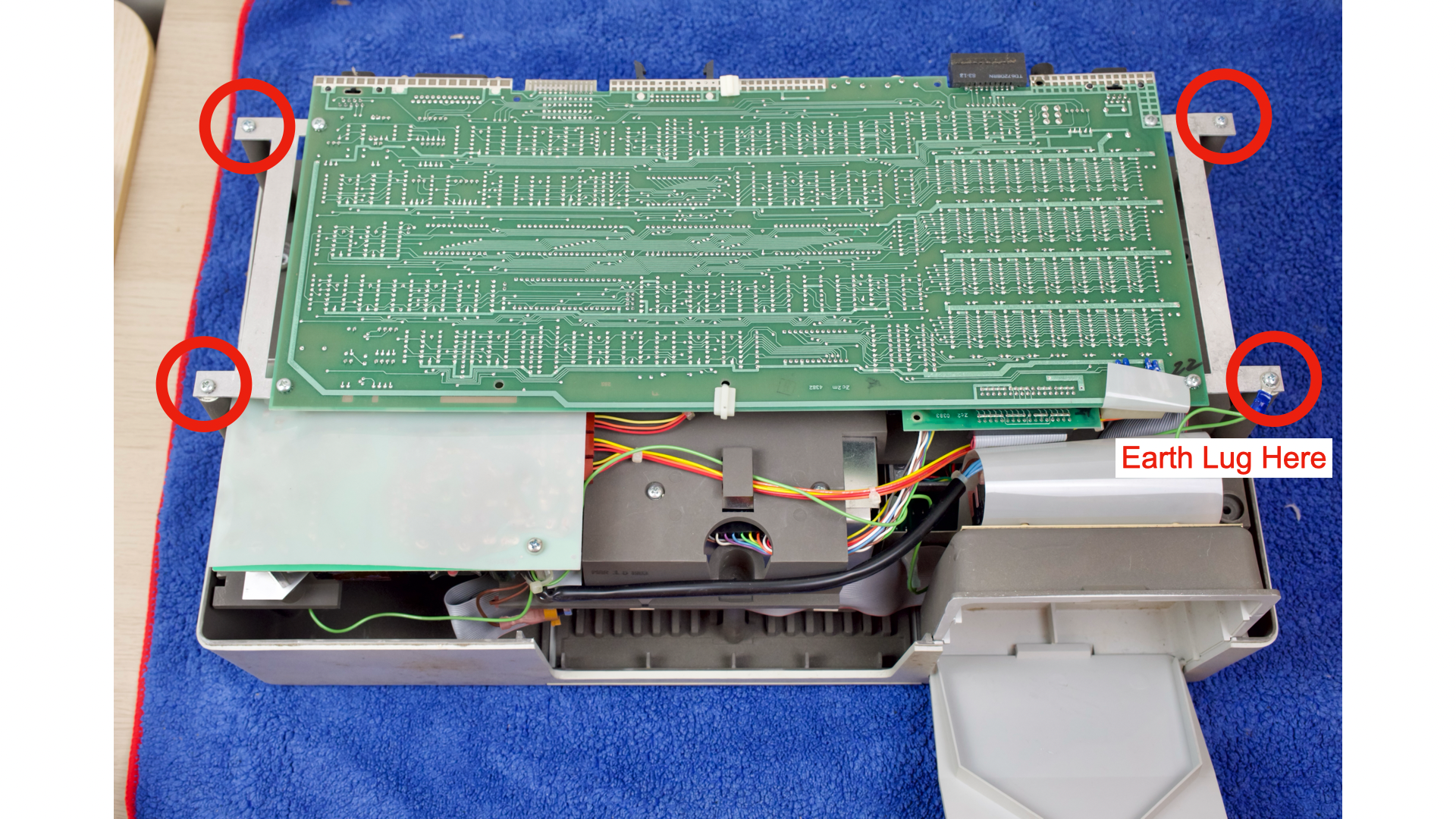
- Unplug any power cables from the right edge
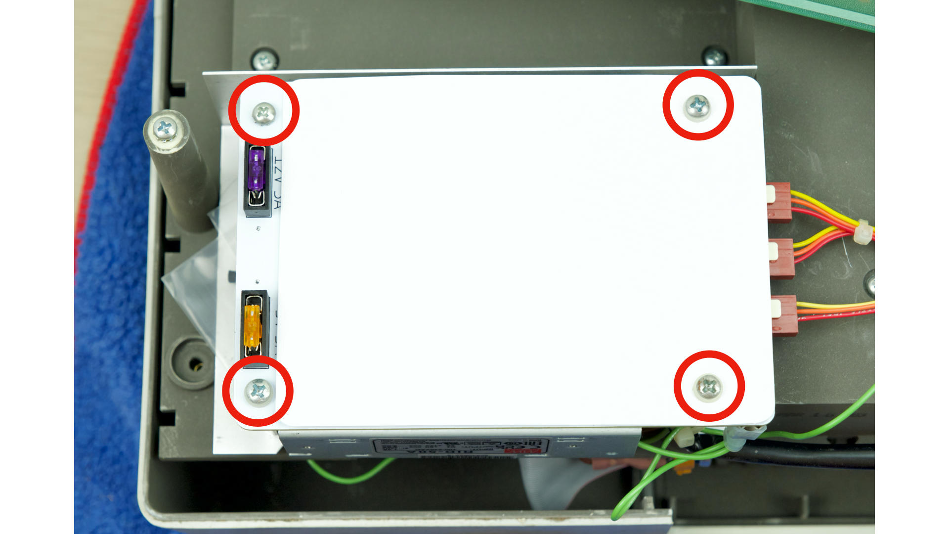
- Undo four screws (two under the insulation sheet)
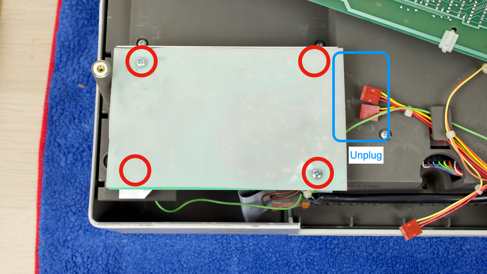
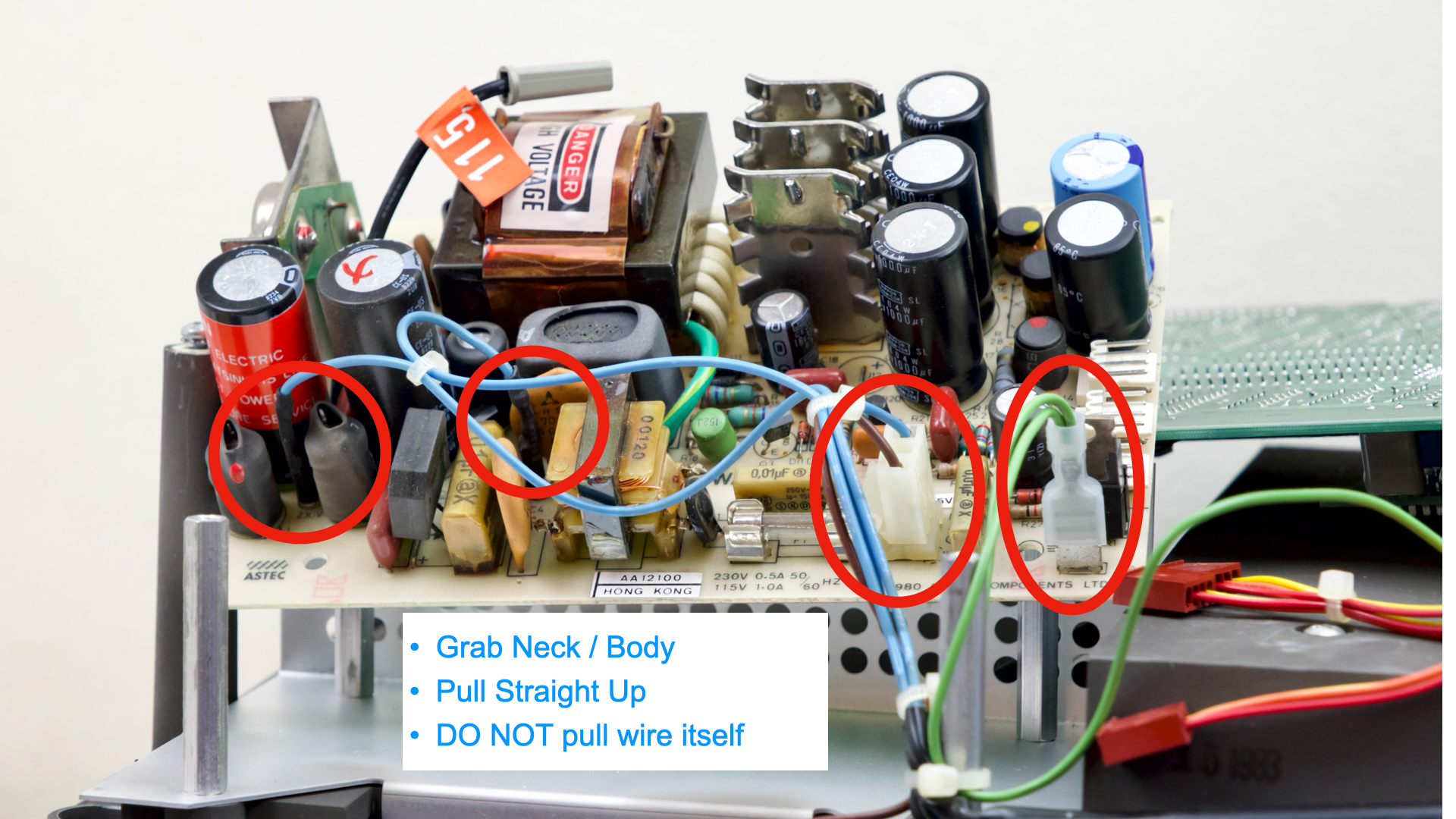
- Flip over old PSU
- Unplug the connectors shown
- Grab neck / body
- Wiggle & Pull straight up
- DO NOT pull on wire itself
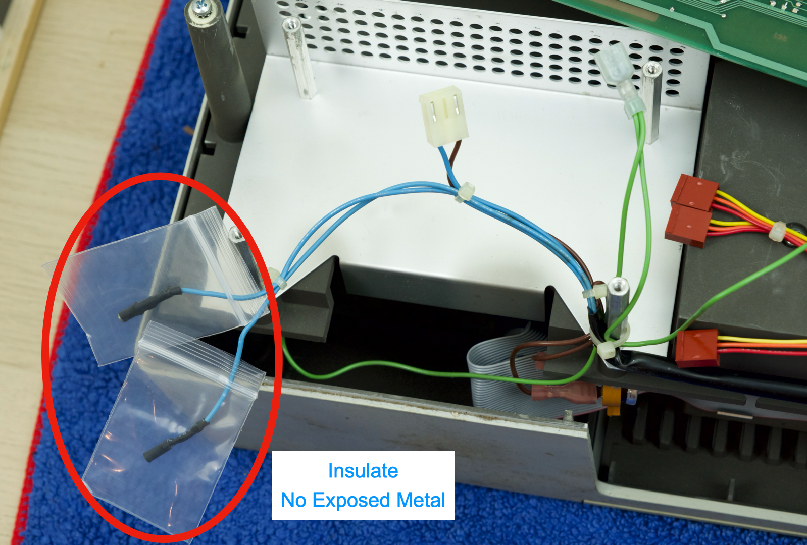
- Remove the old PSU
- Insulate the two loose wires, ensure NO EXPOSED METAL.
- Electric tape, heat shrink, zip bags…
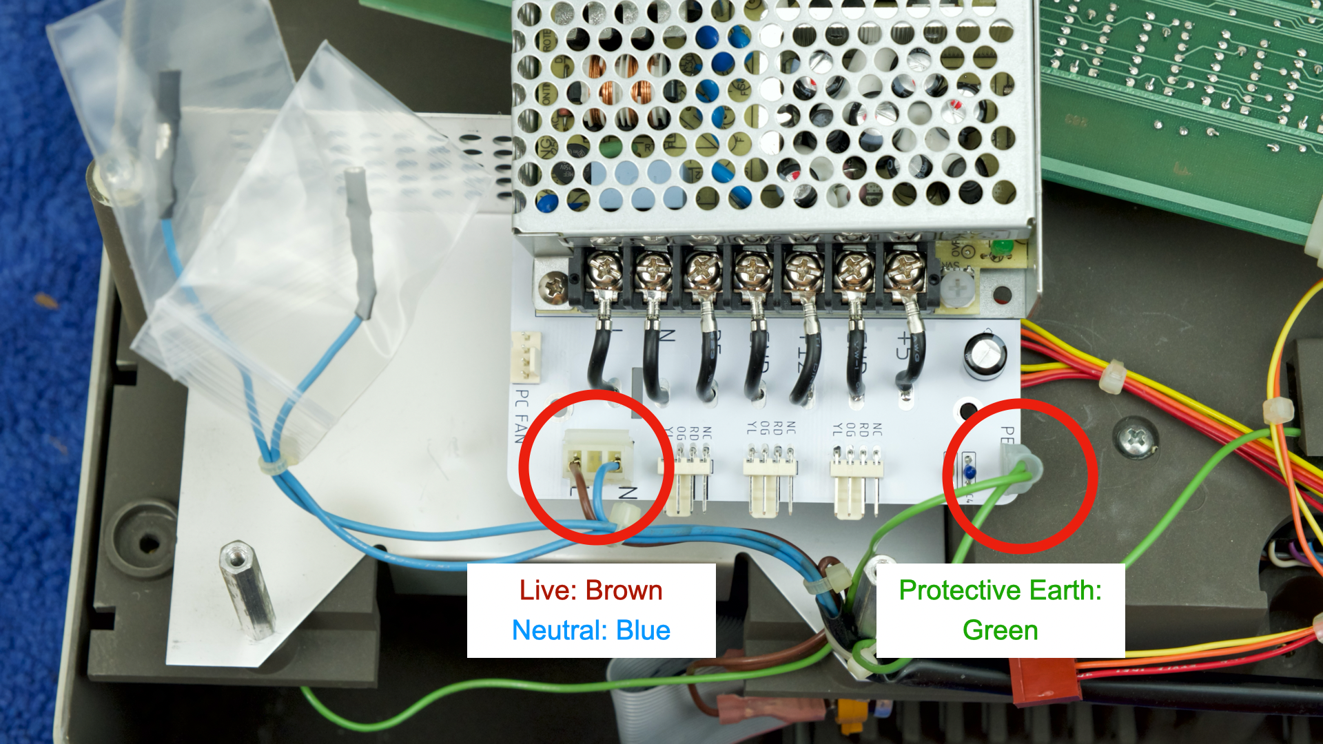
- Offer up the new PSU
- Plug in AC connector
- Black / Brown: Live
- White / Blue: Neutral
- Plug in Earthing Lug
- Green
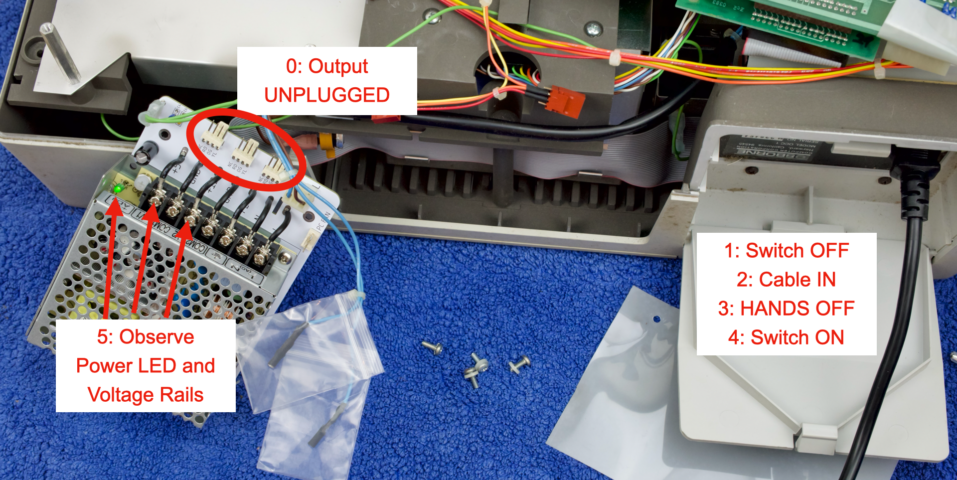
At this stage we can have a quick test
- Leave output unconnected
- Make sure switch is OFF
- Plug in cable
- DON’T TOUCH ANYTHING ELSE
- Flip switch ON
If all goes well:
- Power LED should come on
+V1terminal should be+5V+V2terminal should be+12V- ⚡⚡ MAINS VOLTAGE present on the terminal block
- Only attempt to measure if you know what you’re doing
- TURN OFF POWER AND UNPLUG
- Flip over the PCB
- Rest on the posts
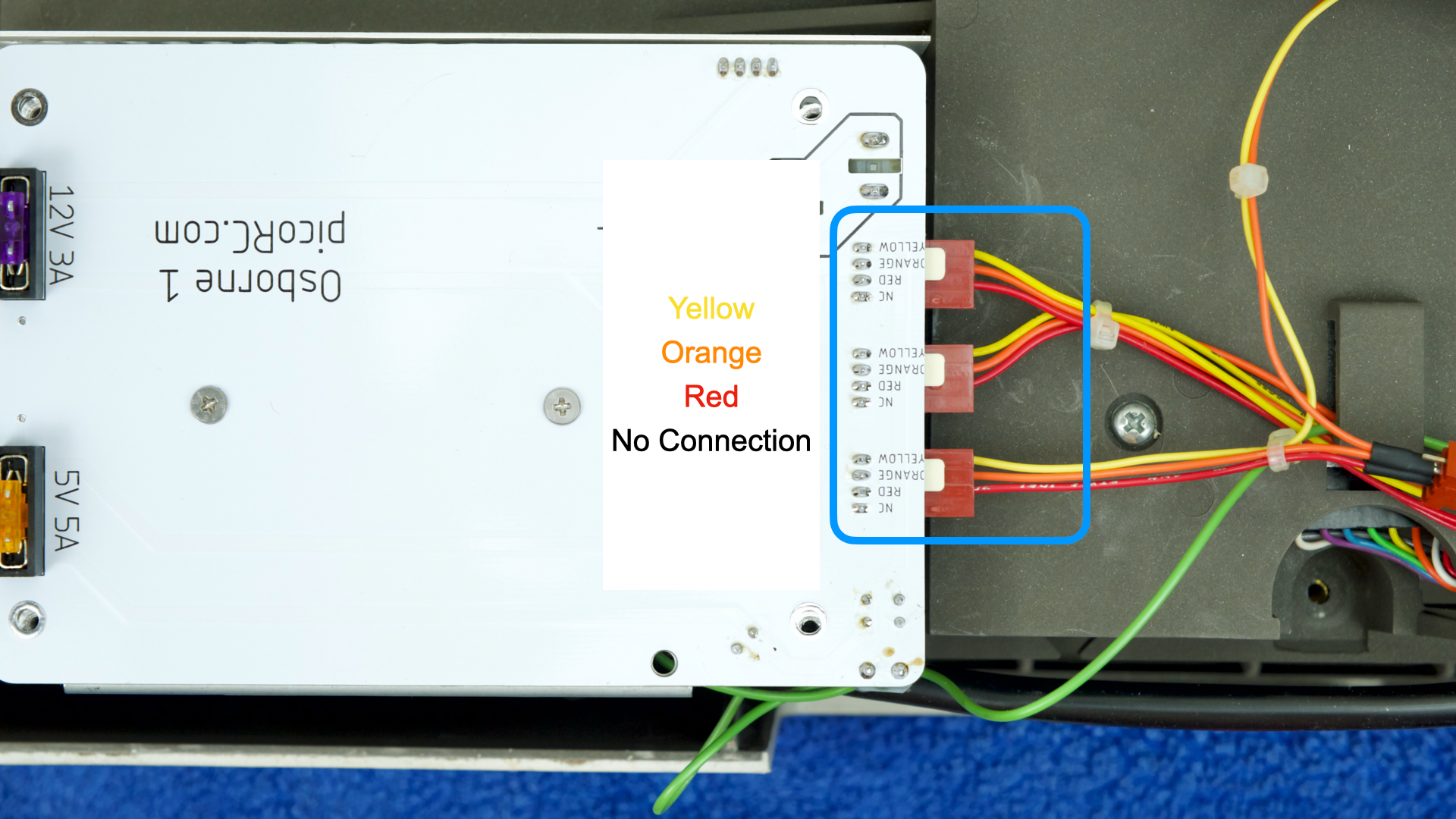
- Plug in the power connectors
- Ensure COLOURS MATCH
- Reinstall the screws
- Secure the insulation sheet with the rightmost screws
- That’s pretty much it!
- Re-secure the motherboard
- Take a breath and turn it on
Next Steps
Several things may happen:
- It beeps and just works
- Possible but rare
- It beeps but garbled screen
- Usually bad RAM
- Nothing happens
- Measure voltage at fuse holder
- Stable voltage
- Turn up brightness / contrast
- Still nothing? Fault on MB (likely RAM) / CRT board.
- No voltage / Voltage jumping around
- Dead short somewhere, PSU in protection mode.
- Most likely tantalum cap on +12V / -12V
- ⚠️TURN OFF AND UNPLUG⚠️ before start working on the computer!
Even if works, might as well do a little maintenance while you’re in there!
- Clean / lube floppy
- Blow out dust
- Inspect CRT board for cold solder joints, etc
Reassemble
- Follow the instructions in reverse to reassemble
Congratulations!
Hopefully with the new PSU and maintenance, your Osborne 1 is now fully functional, enjoy!
Questions or Comments?
Feel free to ask in official Discord Chatroom, raise a Github issue, or email dekunukem gmail.com!